


i. Overview
ii. Combining data from the different mission phases
iii. Updates to the Atlas Image generation process
1. Throughput matching and time-dependent zero-point adjustments
2. Moon contamination processing
3. Pixel outlier detection and masking
4. Saturated pixel expansion
5. Additional FITS header metadata
iv. Attenuated coverage for polar tiles
Atlas Images in the AllWISE data release were generated using the same methodology as for the 4-band (All-Sky) cryo release outlined in section IV.4.f. The AllWISE Atlas was built using the same tiling geometry as described in section IV.4.f.1. Below we outline updates made to the multiframe pipeline to support the generation of Atlas Image (co-adds). Caveats and cautionary notes for the AllWISE Image Atlas are outlined in section IV.4. and the FITS header metadata are described in section IV.1.b.
The single exposure (frame) data included in generating the AllWISE image Atlas is summarized in section V.1.b. Overall, the single-exposures used are new reprocessed products from the 4-band cryo (W1, W2, W3, and W4) and 3-band cryo phases (only W1 and W2), and those from the post-cryo phase (W1 and W2) that were part of the 2013 Post-Cryo Data Release. Similar to previous data releases, the single-exposures were filtered according to whether any were too close to an anneal (nominally 2000 sec; see V.1.b), had a bad quality score (from frame-level QA performed during the second processing pass for the All-Sky release), or were part of dedicated experiments throughout the mission. Furthermore, frame pixels that were tagged in the frame bit-masks as saturated, outliers (e.g., cosmic rays), noisy, or "bad" due to inaccurate calibrations were omitted from co-addition and downstream source extraction in the multiframe pipeline.
The method used to compute photometric zero point (ZP) corrections (dZP) for frames over all mission phases is outlined in section V.3.e. The single-exposure ZPs normally would have been assigned earlier in frame processing, however, after thorough photometric analyses and trending following the availability of vastly more data from the intial processing phases, we discovered inaccuracies in the original single-exposure ZPs.
We updated the multiframe pipeline to correct the incoming frame ZPs using more refined (pre-interpolated) dZP corrections from a look-up table prior to throughput matching them to a common (target) photometric zero-point. The corrections were applied to the incoming (old) frame ZPs according to:
ZPnew = ZPold + dZP(MJD),where dZP(MJD) is the linearly interpolated ZP correction from the refined look-up table for the input frame's midpoint observation time (MJD). The refined dZP values in this look-up table were computed from the coarsely sampled dZP data using the non-parametric loess method - basically a local polynomial regression fit. Figure 1 compares the input dZP measurements with the refined dZPs (resampled at 0.1 sec resolution) predicted from the loess fits. The MJD range shown here covers only the 3-band cryo and 2-band post-cryo mission phases. This is where the variation in dZP as a function of time was largest. The only ZP corrections performed to input frames from the 4-band cryo phase were to W1 where a constant of 0.011 mag was added to all W1 frames. As a reminder (see above), W3 frames from the 3-band cryo phase were not used in AllWISE processing. They are shown here for completeness (red points and lines).
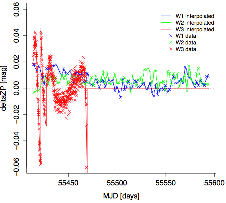 |
| Figure 1 - Delta ZP corrections versus Modified Julian Date showing input estimates (crosses) and "smoothed" interpolated values (lines). Not shown here is the constant offset of dZP = 0.011 mag added to all W1 frame zero point values in the 4-band cryo phase. Only the 3-band cryo and 2-band post-cryo mission phases are shown. Click to enlarge. |
The framework for eliminating frames severely contaminated by scattered moon-light was described in detail in section IV.4.f.iv of the All-Sky Explanatory Supplement. The only change for AllWISE multiframe processing was the retuning of the W2 prior moon-mask and associated parameters. The purpose was to optimize the science applications that relied on having good quality, high signal-to-noise data in this band. This was also motivated by the fact that AllWISE included at least twice the depth-of-coverage (for bands W1 and W2 only) than the 4-band cryo (All-Sky release) Atlas Images. This meant we could afford to lower thresholds and be more aggressive in rejecting frames contaminated by moon-light without severely degrading the overall signal-to-noise.
The W2 moon-centric
mask was updated from a diameter of 44° to 47.4°
(see Figure 2).
Furthermore, the internal moon-filtering parameters for W2:
mfrac, mpct, and nsig defined in section
IV.4.f.iv.2.
were made more aggressive in the sense that more W2
frames with contaminated moon-light were rejected from
co-addition. The new W2 parameter settings for AllWISE are:
mfrac = 0.05, mpct = 0.0001 and nsig = 1.0.
Previously (for the All-Sky and 3-band cryo releases), these
parameters were 0.4, 0.001, and 1.5 respectively.
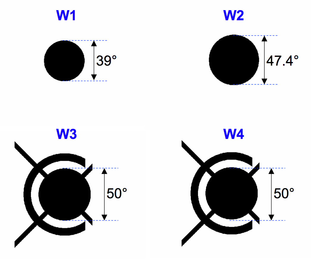 |
| Figure 2 - Smoothed moon-masks for each band to support AllWISE multiframe processing. |
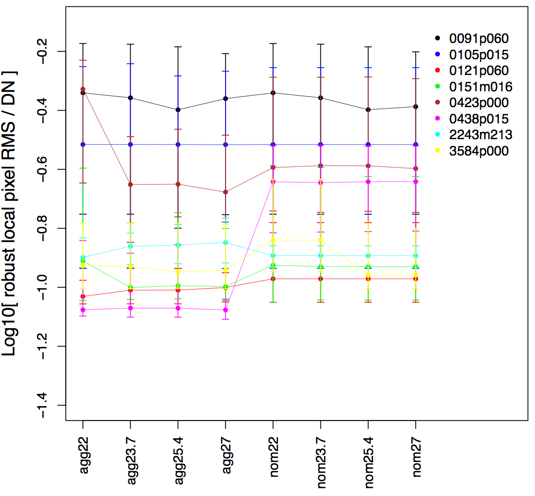
The W2 moon-filtering parameters (and moon-mask size) were empirically tuned using nine test Atlas Images from fields selected to serve various science applications and with a grid of parameters defined as follows:
 agg22   = 22.0° mask & more aggressive filtering params
 agg23.7 = 23.7° mask & more aggressive filtering params
 agg25.4 = 25.4° mask & more aggressive filtering params
 agg27   = 27.0° mask & more aggressive filtering params
 nom22   = 22.0° mask & All-Sky-release filtering parameters
 nom23.7 = 23.7° mask & All-Sky-release filtering parameters
 nom25.4 = 25.4° mask & All-Sky-release filtering parameters
 nom27   = 27.0° mask & All-Sky-release filtering parameters
where the moon-mask dimensions are radii.
Figures 3 and 4 show the local robust
intensity-pixel RMS on the various W2 Atlas Images generated for
each parameter set above (labelled horizontally).
Two flavors of robust RMS metrics were computed:
(i) based on the local 50% - 15.86% value using only pixels
centered around the median depth-of-coverage and computed
within 3x3 square partitions on each tile (Figure 3) and
(ii) a trimmed lower-tail standard-deviation from the mode,
also using only pixels around the median-depth and within
3x3 partitions (Figure 4).
The vertical bars are not error bars, but the minimum and maximum RMS values
over all tile partitions. The dots are medians over all partitions.
The second metric (Figure 4) is expected to be
more immune to the presence of sources and bright structure.
Nonetheless, both metrics complement each other and are
qualitatively consistent. The conclusion is that the more
agressive moon-filtering parameters lead to a smaller overall
pixel RMS in the Atlas Images. This means that moon-contaminated
frames (admitted with the "nominal" less aggressive parameters)
lead to elevated levels of Poisson (shot) noise in the Atlas Images.
Furthermore, the greater loss of frames for the more aggressive filtering is
not enough to inflate the overall noise after stacking relative
to the less-aggressive filtering. When present, moon-light appears to
dominate the overall intensity-pixel RMS.
 |
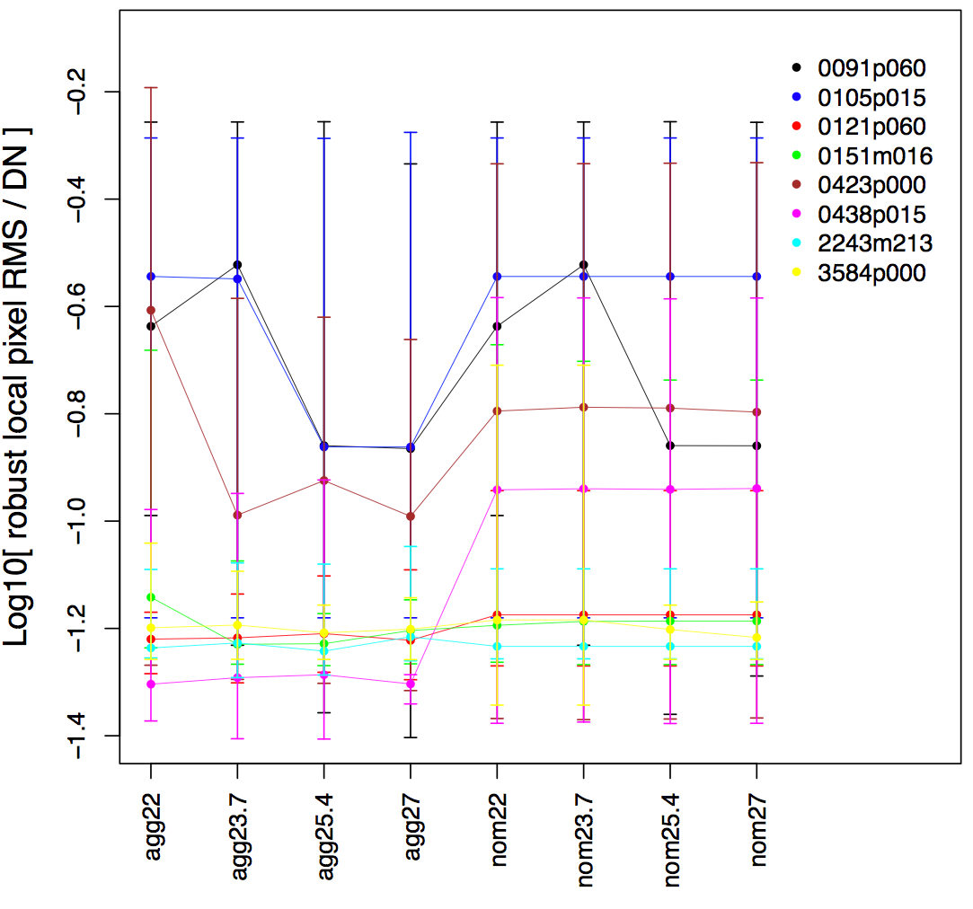 |
| Figure 3 - Robust intensity-pixel RMS on W2 Atlas Images using the 50-16 percentile difference as a function of moon-mask radius and different filtering parameters. See text. Click to enlarge. | Figure 4 - Robust intensity-pixel RMS on W2 Atlas Images using the lower-tail standard-deviation from the mode as a function of moon-mask radius and different filtering parameters. See text. Click to enlarge. |
Another metric we explored (analogous to Figures 3 and 4)
was the W2 single-exposure photometric sensitivity limit, estimated
from the stack-RMS in repeated single-exposure source
measurements. This is based on the
w2sigP1
catalog metric. The RMS values were converted to 5-sigma magnitude limits
for all nine test Atlas Images and the same set of moon-filtering parameters.
The results are shown in Figure 5.
The overall trend is quite clear. More aggressive moon-filtering
gets us deeper in general despite the loss in frame-depth
than if more moon-contaminated frames are used in the stack.
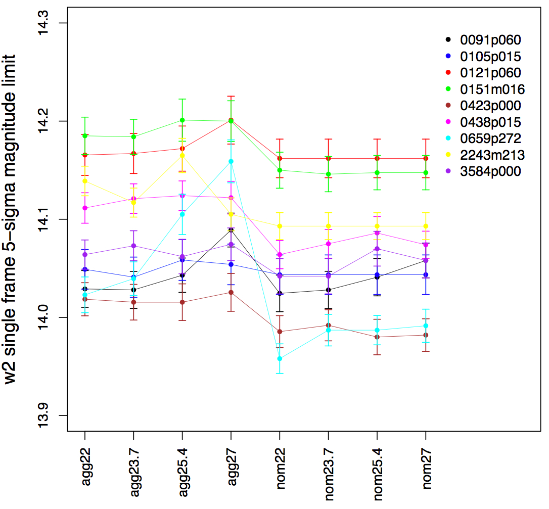 |
| Figure 5 - W2 single-exposure photometric sensitivity based on the RMS in repeatability (w2sigP1 catalog metric) as a function of moon-mask radius and different filtering parameters. See text. Click to enlarge. |
Similar to the All-Sky release Image Atlas, the number of frames suspected to contain moon-glow (as determined from the prior moon-mask alone) is stored as the "MOONINP" keyword in the Atlas Image FITS headers. Furthermore, the actual number of frames rejected (after all filtering) is stored as the "MOONREJ" keyword.
Details of the pixel-outlier detection method are described in section IV.4.f.v of the All-Sky Explanatory Supplement.
The only update for AllWISE was a fix to a problem reported in section I.4.c.ix. of the cautionary notes for the All-Sky Image Atlas. The specific problem refers to the erroneous masking of "dark" (dust-obscured) regions in the galactic plane, or more specifically, wherever there's a large dynamic range in pixel signals. The problem arose from inadvertent clipping of negative pixel values after in-frame medians were subtracted from the respective input frames and pixel values therein placed on a logarithmic scale and converted to 16-bit integer values to minimize memory usage when stacking. This clipping was usually avoided by adding a global offset to all the input frames to ensure positivity before the logarithmic conversion, but there were some regions on the sky where this correction was not enough. The appropriate regularization constants were adjusted so that this clipping would not occur during the outlier-detection step.
As described in section VII.3.b.iv.1 of the All-Sky Explanatory Supplement, the on-board saturation tagging was unreliable throughout the mission for all bands. Sources (or regions) which were expected to be saturated often had unflagged pixels with values that were nonsense.
To mitigate (or rather ameliorate) this effect, we implemented a pre-processing step whereby pixels masked upstream as saturated by the on-board encoding (specifically tagged with any frame mask bits 10 to 19) were spatially expanded if their local density exceeded a threshold (see below). This ensured more complete blanketing of partially saturation-masked regions. The input frame masks were then updated with additional masked pixels to omit from co-addition and source extraction down-stream.
There are three input parameters that control the frequency and amount of expansion: neis, nszs, and exps. These operate as follows. If a frame pixel was tagged as saturated upstream and a region of size "nszs x nszs" pixels centered on it contains > neis additional saturated pixels (where neis ≤ nszs x nszs), expansion will be triggered around all pixels initially tagged as saturated in this region. This entails blanketing "(exps x exps) - 1" additional pixels around each saturated (input seed) in the frame mask. The values of these parameters in AllWISE processing were neis = 7, nszs = 5, and exps = 3. Figure 6 illustrates the mechanism.
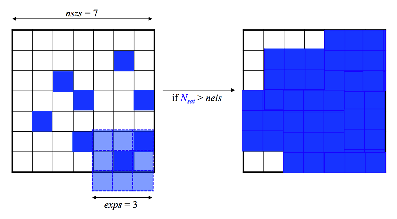 |
| Figure 6 - Schematic of saturated-pixel expansion method. Nsat is the number of saturated pixels initially tagged within the region nszs x nszs. If this number exceeds some threshold neis, an additional (exps x exps) - 1 pixels are masked around each pre-existing saturated seed. On the right is the final blanketed region. |
Note: this attempted "saturation blanketing" was not enough at times. It only helped reduce the number of unmasked saturated pixels. It was performed conservatively as to not impact the source photometry. In fact, the only impact was to bright sources that were already in the saturated regime, i.e., had at least one saturated pixel in their core. The effect of masking more pixels in an already saturated core leads to a reduction in the PSF-fitted flux by a few-tenths of a magnitude at most. That is, as more weight is given to the PSF wings, the flux is reduced. This behavior is not understood.
The additional keywords included in the FITS headers of AllWISE Atlas Image products are measures of the difference between PSF-fit Source Catalog positions and flux-weighted source positions derived directly from the intensity image. In general, these differences were found to be non-zero and statistically significant, and varied with position on the sky as well as across bands. For details on the possible causes, see section IV.3.b. Section IV.3.b. also describes how to use these measures to correct the global astrometry of an Atlas Image, for example, if one intends to perform their own source extraction from the Atlas Images. Here's an example of the new keyword metadata:
FLXWTNUM=                 1652 / number of sources used to compute centroids
FLXWTDX =            0.0102941 / [arcsec] mdex - flux-weighted centroid along X
FLXWTUDX=            0.0033332 / [arcsec] 1-sigma uncertainty in flxwtdx
FLXWTSDX=            3.0883285 / signal-to-noise ratio in flxwtdx
FLXWTDY =            0.0373456 / [arcsec] mdex - flux-weighted centroid along Y
FLXWTUDY=            0.0033118 / [arcsec] 1-sigma uncertainty in flxwtdy
FLXWTSDY=           11.2765188 / signal-to-noise ratio in flxwtdy
"mdex" refers to Source Catalog positions determined
from PSF-fit photometry
in the multiframe source extraction pipeline.
To ensure accurate flux-weighted centroids, a "clean" subset of the
sources extracted per Atlas Image are used. The band-dependent
filtering metrics used to select sources for computing the
position offset metadata are given in Table 1.
| Band | min w?mpro [mag] |
max w?mpro [mag] |
min w?rchi2 | max w?rchi2 | min w?snr | w?sigmpro | na | nb |
|---|---|---|---|---|---|---|---|---|
| 1 | 7.0 | 13.7 | 0.5 | 1.8 | 7.5 | not 'null' | 0 | 1 |
| 2 | 6.0 | 13.0 | 0.5 | 1.8 | 7.5 | not 'null' | 0 | 1 |
| 3 | 3.0 | 10.2 | 0.2 | 2.6 | 6.0 | not 'null' | 0 | 1 |
| 4 | 2.5 | 7.0 | 0.1 | 3.0 | 6.0 | not 'null' | 0 | 1 |
After filtering the Atlas Image source-extraction table, flux-weighted centroids (Xc, Yc) are computed for each source along each axis:
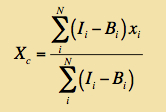 |
(Eq. 1) |
The background-subtracted pixel fluxes (Ii - Bi) are computed over N pixels within apertures of radius 8.5 arcsec for W1, W2, W3 and 13 arcsec for W4 and placed on the PSF-fitted position from the input extraction table. The pixel backgrounds Bi are estimated from the median signal within an annulus of width 2.75 arcsec (for all bands) surrounding the aperture, i.e., all N pixels in the aperture are assigned this median value. This background estimate need not be the "true" background. Contamination by a small amount of source flux will not significantly affect the centroid accuracy.
After all flux-weighted centroids are computed, they are differenced with the input PSF-fit positions and median X, Y offsets are computed over the entire image. The uncertainties in these global offsets are based on a robust RMS over all source offsets per axis divided by sqrt(number of sources used). If the flux-weighted centroids could not be computed for an Atlas Image (e.g., due to an absence of sources after filtering), the position offset metadata are assigned 'null'.
As for the All-Sky Release, some Tiles needed to have their coverage reduced so they can be processed by the source extractor. The attenuation process for AllWISE followed the same algorithm used for the All-sky release (c.f. All-Sky Release Supp. V.2.d).
For AllWISE, the selection criteria for Tiles to be attenuated was:
As for the All-Sky Release, the target frame depth at any given point was 165 frames. This target is applied in each band independently. For AllWISE, this means that whereas at full depth W1 and W2 are about twice as deep as W3 and W4, after attenuation all bands will have about the same depth. This also means that the sampling rate for W3 and W4 (frames used per unit time) is twice that of W1 and W2 since usable W3 and W4 frames only span (roughly) the first half of the mission.
Full depth versions of Atlas Images are available for these Tiles but without any source extraction products. See IV.5.
| 0791m682_ac51 | 0795m697_ac51 | 0803m652_ac51 | 0816m667_ac51 |
| 0825m637_ac51 | 0830m682_ac51 | 0837m697_ac51 | 0838m652_ac51 |
| 0852m621_ac51 | 0853m667_ac51 | 0855m712_ac51 | 0858m637_ac51 |
| 0870m682_ac51 | 0873m652_ac51 | 0879m697_ac51 | 0884m621_ac51 |
| 0890m667_ac51 | 0891m637_ac51 | 0900m712_ac51 | 0908m652_ac51 |
| 0909m682_ac51 | 0915m621_ac51 | 0920m697_ac51 | 0924m637_ac51 |
| 0927m667_ac51 | 0943m652_ac51 | 0945m712_ac51 | 0947m621_ac51 |
| 0949m682_ac51 | 0957m637_ac51 | 0962m697_ac51 | 0964m667_ac51 |
| 0978m652_ac51 | 0988m682_ac51 | 0990m637_ac51 | 1002m667_ac51 |
| 1004m697_ac51 | 2595p696_ac51 | 2597p666_ac51 | 2609p636_ac51 |
| 2610p681_ac51 | 2621p651_ac51 | 2635p666_ac51 | 2637p696_ac51 |
| 2642p636_ac51 | 2650p681_ac51 | 2652p620_ac51 | 2655p711_ac51 |
| 2656p651_ac51 | 2672p666_ac51 | 2675p636_ac51 | 2679p696_ac51 |
| 2684p620_ac51 | 2690p681_ac51 | 2691p651_ac51 | 2700p711_ac51 |
| 2708p636_ac51 | 2709p666_ac51 | 2715p620_ac51 | 2721p696_ac51 |
| 2726p651_ac51 | 2729p681_ac51 | 2741p636_ac51 | 2746p666_ac51 |
| 2747p620_ac51 | 2761p651_ac51 | 2762p696_ac51 | 2769p681_ac51 |
| 2774p636_ac51 | 2783p666_ac51 | 2796p651_ac51 | 2804p696_ac51 |
| 2808p681_ac51 |
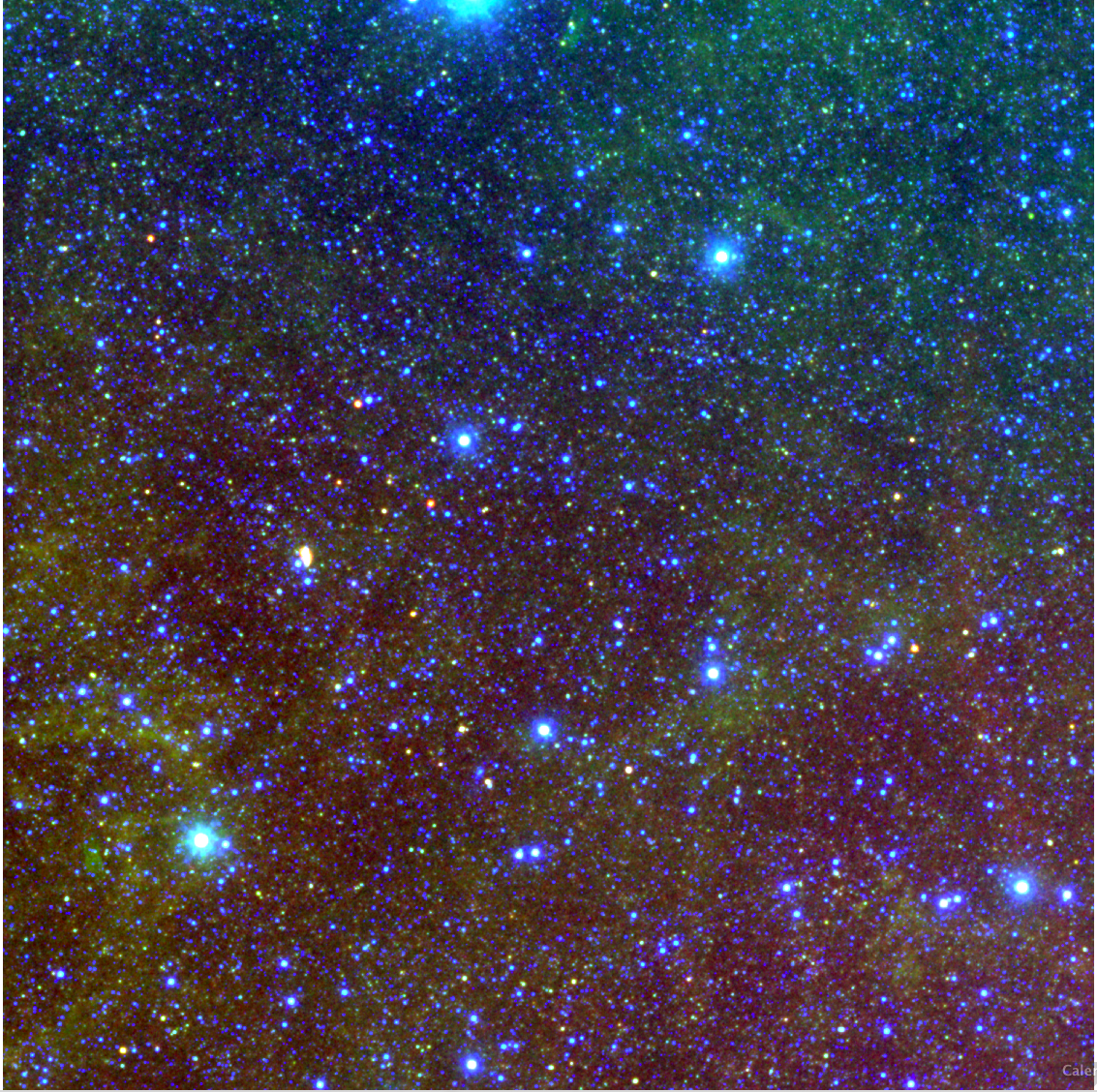
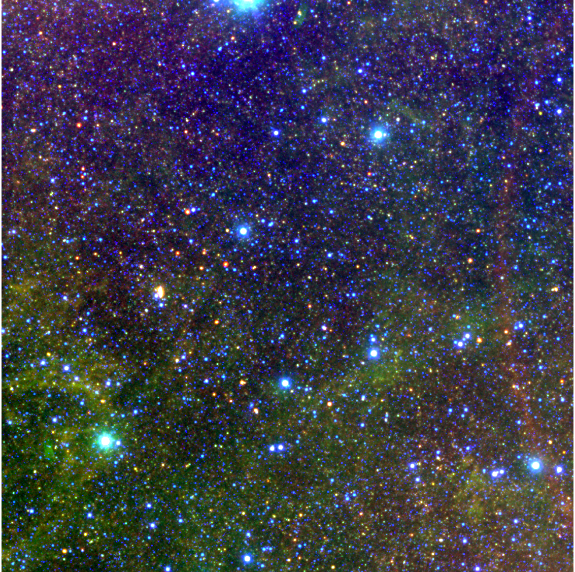
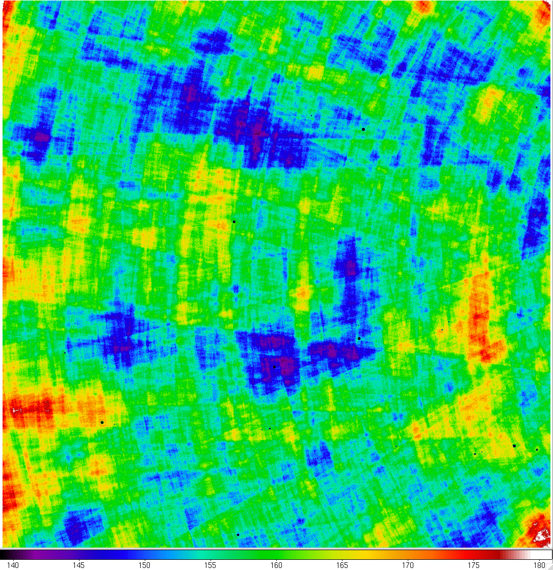
Three-band color-composite images (RGB = W4,W3,W1) of two attenuated AllWISE Atlas Images that cover regions near the North and South Ecliptic Poles (NEP and SEP) are shown in Figures 7a and 7b. For comparison, the full-depth Atlas Images are shown in Figures 7c and 7d. The corresponding pixel depth-of-coverage maps (for W1) are shown in Figures 8a - 8d. Incidentally, the images shown in Figures 7b and 7d (tile ID 0853m667) cover a region on the outskirts of the Large Magellanic Cloud.
The tile near the NEP (tile ID 2746p666 - Figures 7a and 7c) falls
in a region where the single exposures span ~ 8 months, that is, from the
first sky pass (first 6 months of the mission),
then into the second month of the second sky pass. The
W3 and W4 array temperatures and backgrounds began to rise in this
latter phase, perhaps also
inducing small spatial variations in their responsivity. Therefore,
the different pattern in W3 and W4 nebulosity between the attenuated
(Figure 7a) and full depth
(Figure 7c) tiles is very likely due the different
mix of input exposures covering the different mission epochs. The
attenuated tile in this case includes relatively more exposures from
the first six months of the mission where the W3 and W4 instrumental
signatures are more stable and better calibrated.
 |
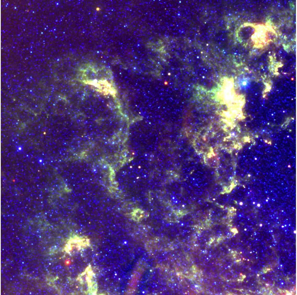 |
| Figure 7a - W1,W3,W4 composite color image of Atlas Image tile 2746p666_ac51 near the NEP with attenuated depth in the AllWISE Release. Corresponding pixel depth-of-coverage map (for W1) is shown in Figure 8a. | Figure 7b - W1,W3,W4 composite color image of Atlas Image tile 0853m667_ac51 near the SEP with attenuated depth in the AllWISE Release. Corresponding pixel depth-of-coverage map (for W1) is shown in Figure 8b. |
 |
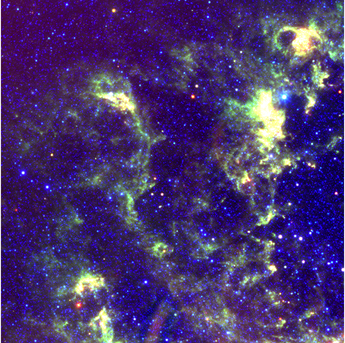 |
| Figure 7c - W1,W3,W4 composite color image of Atlas Image tile 2746p666_ac52 near the NEP with full-depth in the AllWISE Release. Corresponding pixel depth-of-coverage map (for W1) is shown in Figure 8c. | Figure 7d - W1,W3,W4 composite color image of Atlas Image tile 0853m667_ac52 near the SEP with full-depth in the AllWISE Release. Corresponding pixel depth-of-coverage map (for W1) is shown in Figure 8d. |
 |
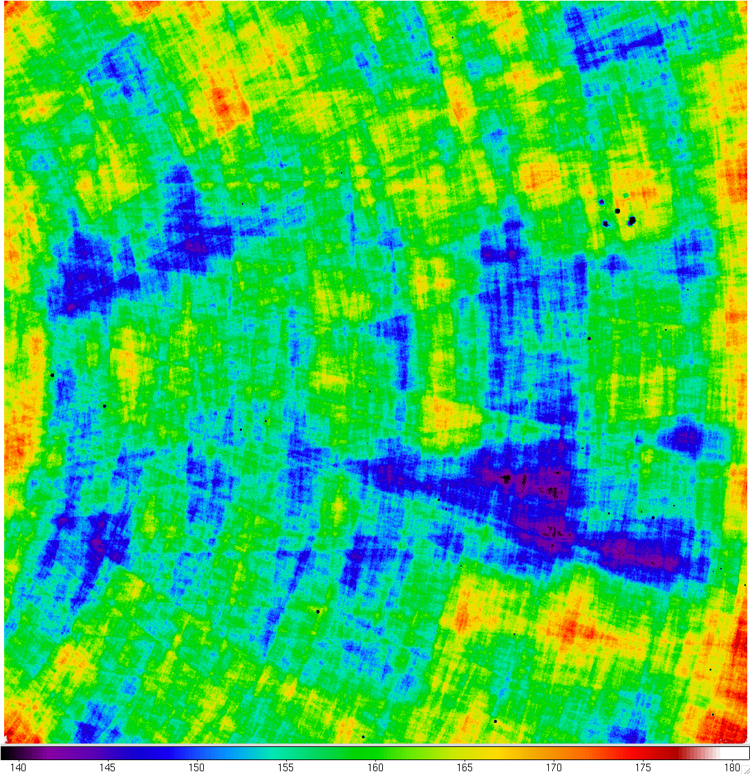 |
| Figure 8a - W1 attenuated pixel depth-of-coverage map for the Atlas Image in Figure 7a. Color-bar gives the approximate depth. Click to enlarge. | Figure 8b - W1 attenuated pixel depth-of-coverage map for the Atlas Image in Figure 7b. Color-bar gives the approximate depth. Click to enlarge. |
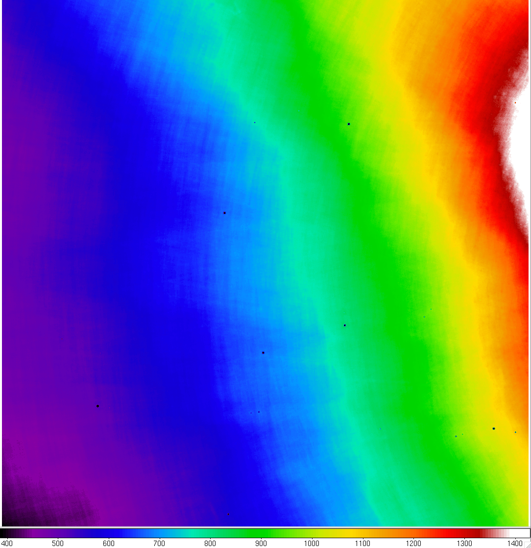 |
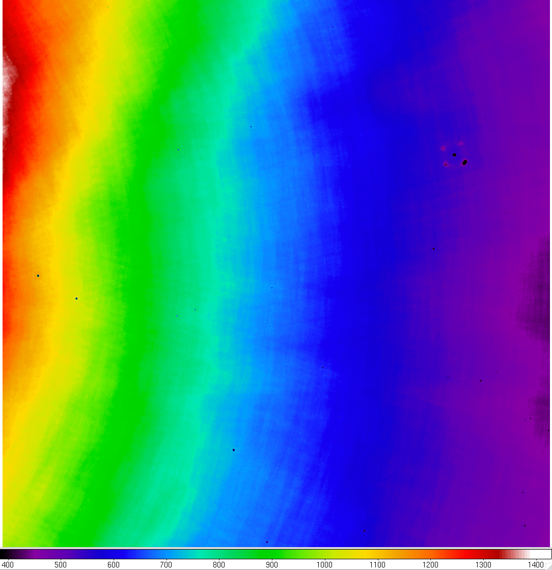 |
| Figure 8c - W1 full-depth pixel depth-of-coverage map for the Atlas Image in Figure 7c. Color-bar gives the approximate depth. Click to enlarge. | Figure 8d - W1 full-depth pixel depth-of-coverage map for the Atlas Image in Figure 7d. Color-bar gives the approximate depth. Click to enlarge. |
Last update: 19 November 2013