


On rare occasions, WISE data exhibit an interesting phenomenon whose nature is unknown. A large annulus of W2 pixels, centered roughly on the pixel at coordinates [912,568] (0-indexed, as in IDL) and hereafter referred to as the "resonant pixel," appears then subsequently decays in later frames. This halo is usually preceded by a dramatic elevation of signal, colloquially referred to as a "TV test pattern" (also of unknown origin), that appears in both W1 and W2. The phenomenon is often accompanied by a W1 latent at approximately the same row as the W2 resonant pixel halo, but on the left side of the array. This W1 latent is generally present in strong instances of the W2 phenomenon.
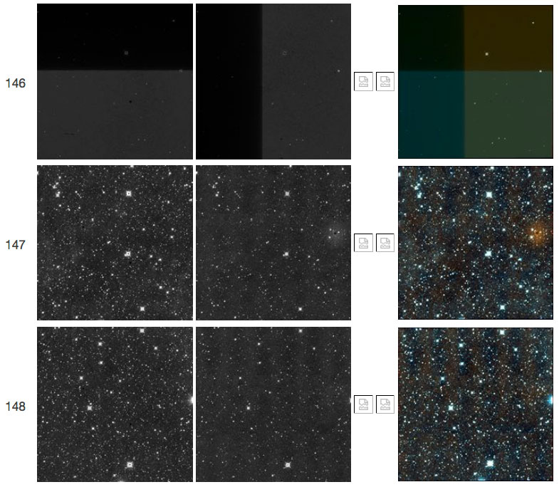
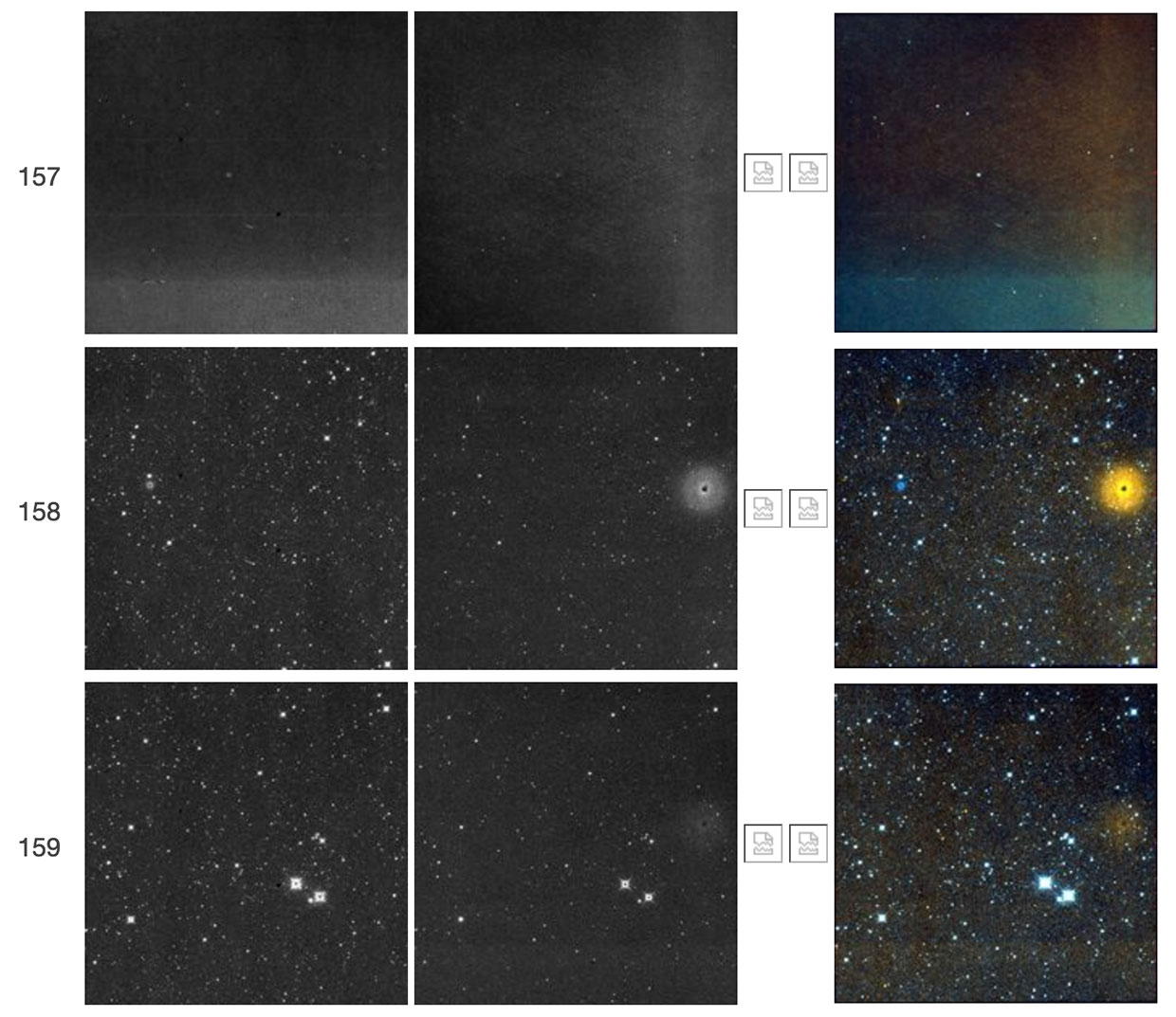
The following figures illustrate, in chronological order, the fifty-two recorded instances of the W2 resonant pixel phenomenon. In all figures, each row represents a simultaneously taken set of frames that, from left to right, represent W1, W2, W3, W4, and a three-color image formed using the W1+W2(+W3+W4) frames. The frame number in the scan is shown to the far left. Icons with open white squares or question marks indicate missing bands of data. For example, data taken during the NEOWISE Reactivation period lack W3 and W4 data.
The first instance of the resonant pixel phenomenon occurred during the WISE 4-band cryogenic period (Figure 1), followed by one instance in the WISE 3-band cryogenic period (Figure 2), three instances during the WISE post-cryogenic period (Figures 3-5), and forty-seven instances during NEOWISE reactivation (Figures 6-52).
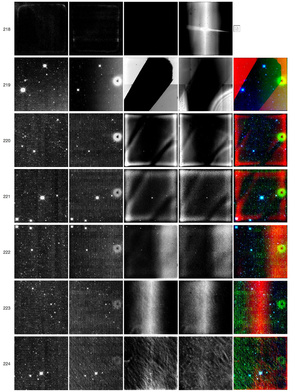 |
| Figure 1 - Scan 06405b, framesets 218-224. Frameset 218, which failed to complete processing and therefore has no color-composite image, shows elevated backgrounds in all four observed bands, which led to most pixels being NaN'ed in W1, W2, and W3. The following framesets, 219-224, show the resonant pixel halo in W2 (second image from the left in each row). A W1 counterpart of the resonant pixel halo in the form of a latent is also visible at approximately the same row as the W2 feature but on the left side of the array. The W1 feature is weaker than the W2 resonant pixel halo and is not always present in other framesets where the latter is seen. |
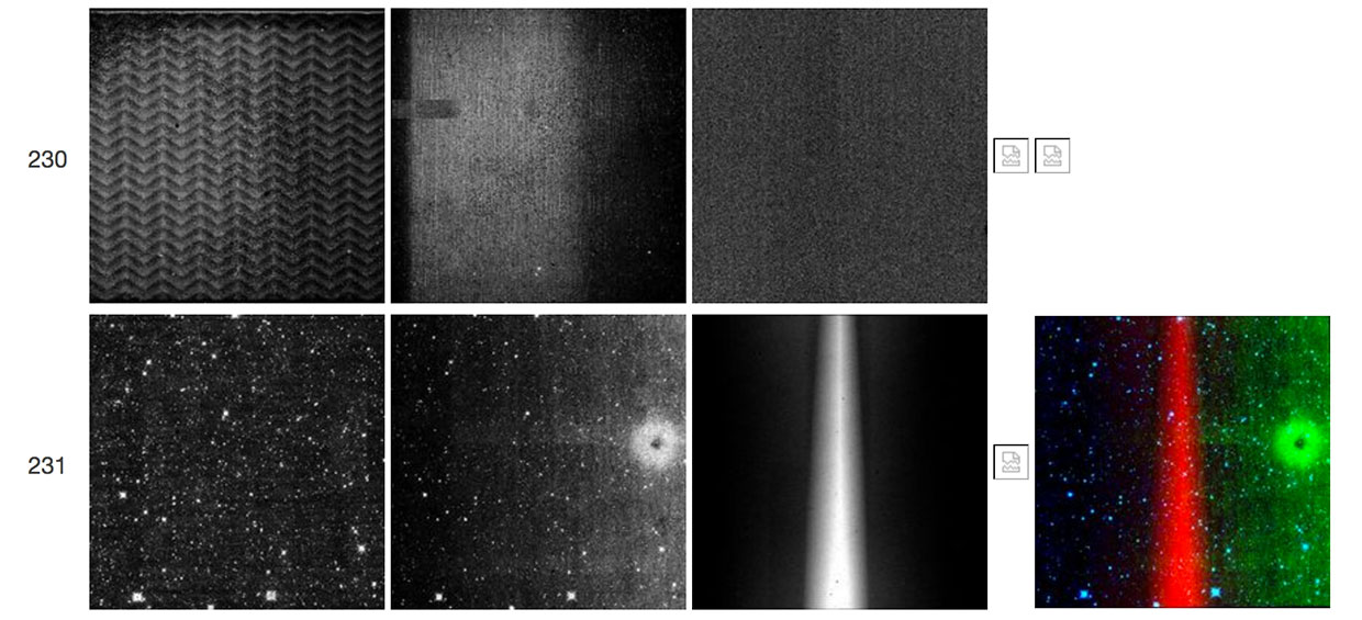 |
| Figure 2 - Scan 07949b, framesets 230-231. Frameset 230, which failed to complete processing and therefore has no color-composite image, shows elevated backgrounds in all three observed bands. The following frameset, 231, shows the resonant pixel halo in W2 (second row, second image from the left). |
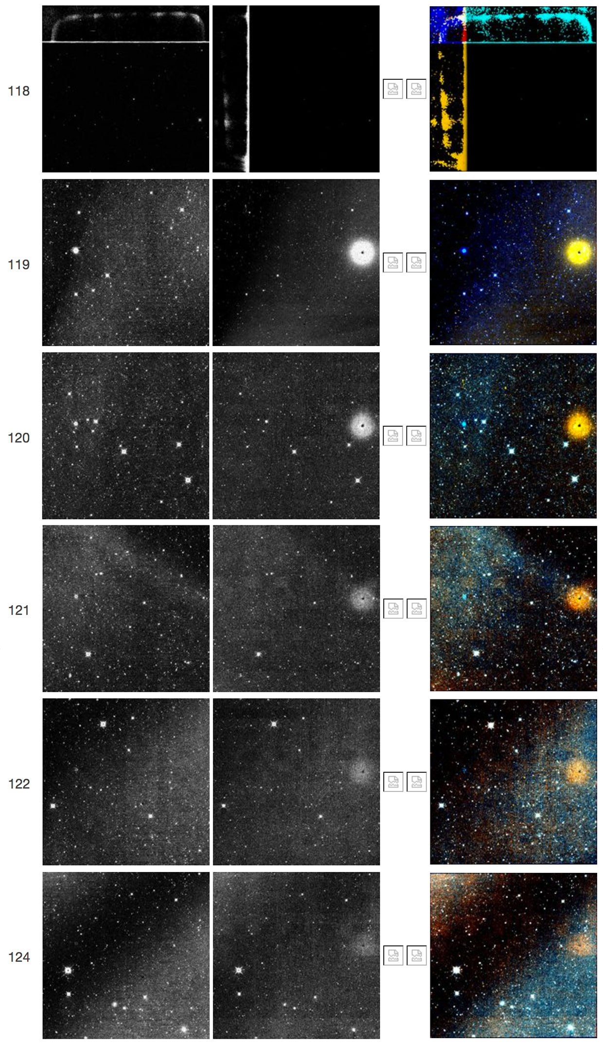 |
| Figure 3 - Scan 10897b, framesets 118-124. Frameset 118 shows elevated backgrounds that led to most of its pixels being NaN'ed. The arrays exhibit evidence of the "TV test pattern," where rectangular blocks (horizontal in W1 and vertical in W2, orthogonal in each case to the read-out channels) show elevated signal; in this case, at the top edge of W1 and on the left edge of W2. Frameset 119 shows the W2 resonant pixel halo, which decays throughout framesets 120-124. The W1 counterpart of the W2 resonant pixel halo is also seen here. |
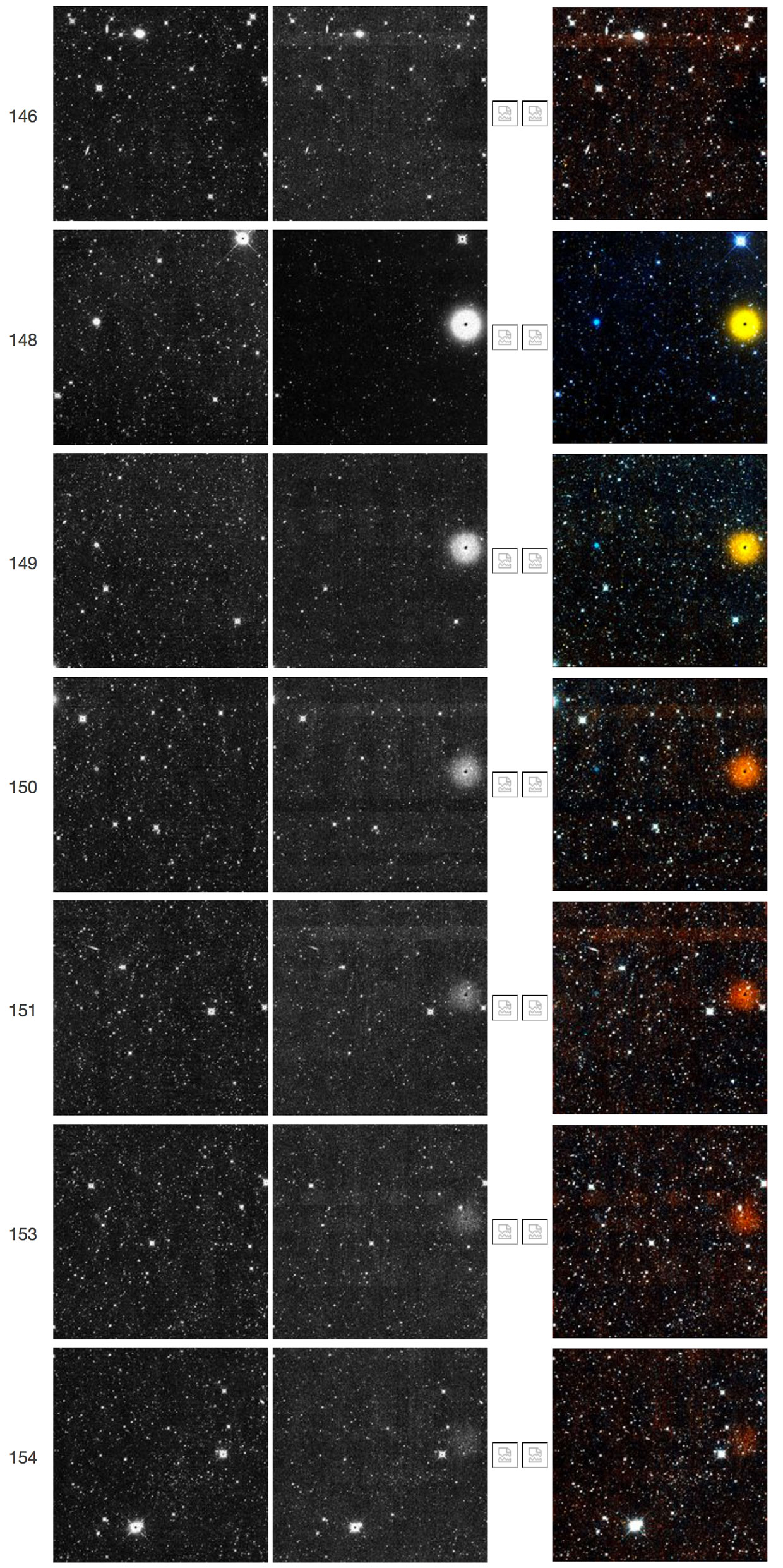 |
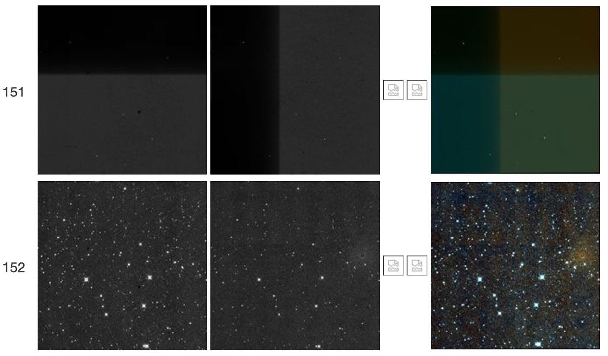
| Figure 4 - Scan 11984a, framesets 146-154. Frameset 146 appears normal. Frameset 147 shows elevated backgrounds but fails in processing and is not illustrated here. Framesets 148-154 show the appearance and decay of the W2 resonant pixel halo. The W1 counterpart of the W2 resonant pixel halo is also seen here. |
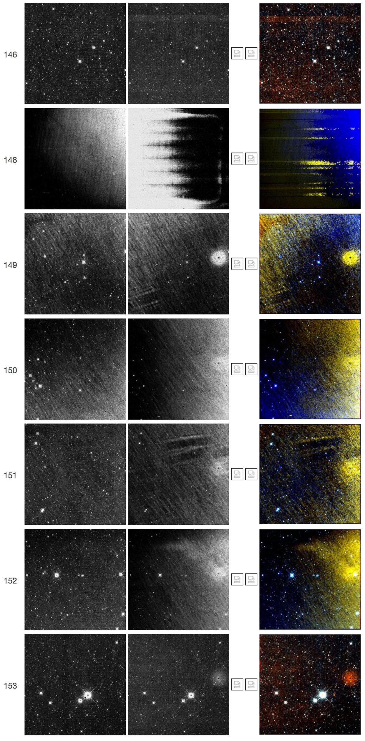 |
| Figure 5 - Scan 12125b, framesets 146-153. Frameset 146 appears normal. Frameset 148 has elevated backgrounds and an unusual illumination pattern. Framesets 149-153 show the appearance and decay of the W2 resonant pixel halo. The W1 counterpart of the W2 resonant pixel halo is also seen here. |
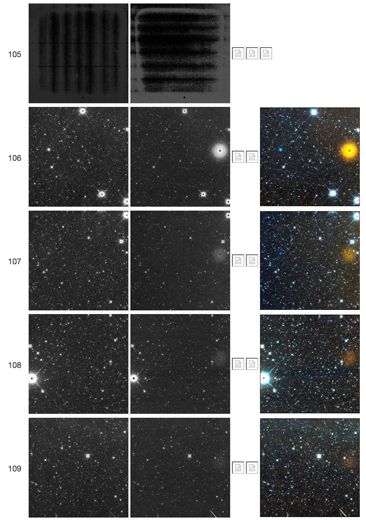 |
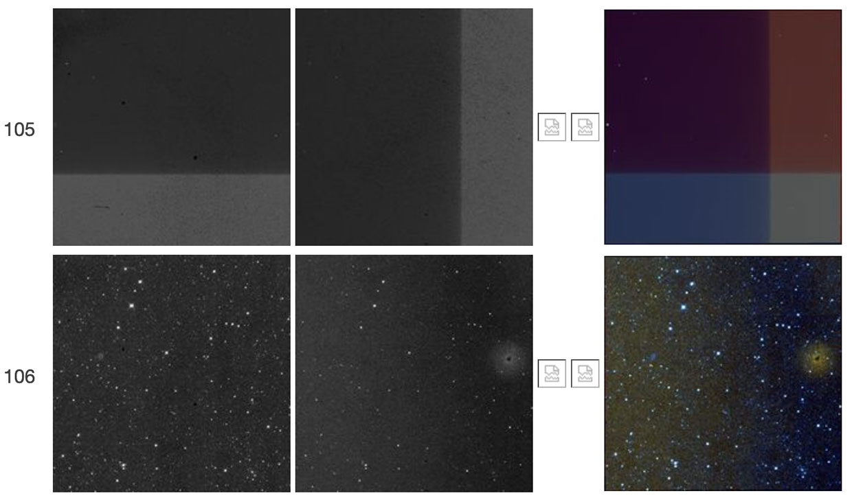
| Figure 6 - Scan 48672a, framesets 105-109. Frameset 105 has high backgrounds and an unusual illumination pattern caused in part by saturation. This frameset also failed to complete processing, so its color-composite image is not available. Framesets 106-109 show the decay of the W2 resonant pixel halo. The W1 counterpart of the W2 resonant pixel halo is also seen here. |
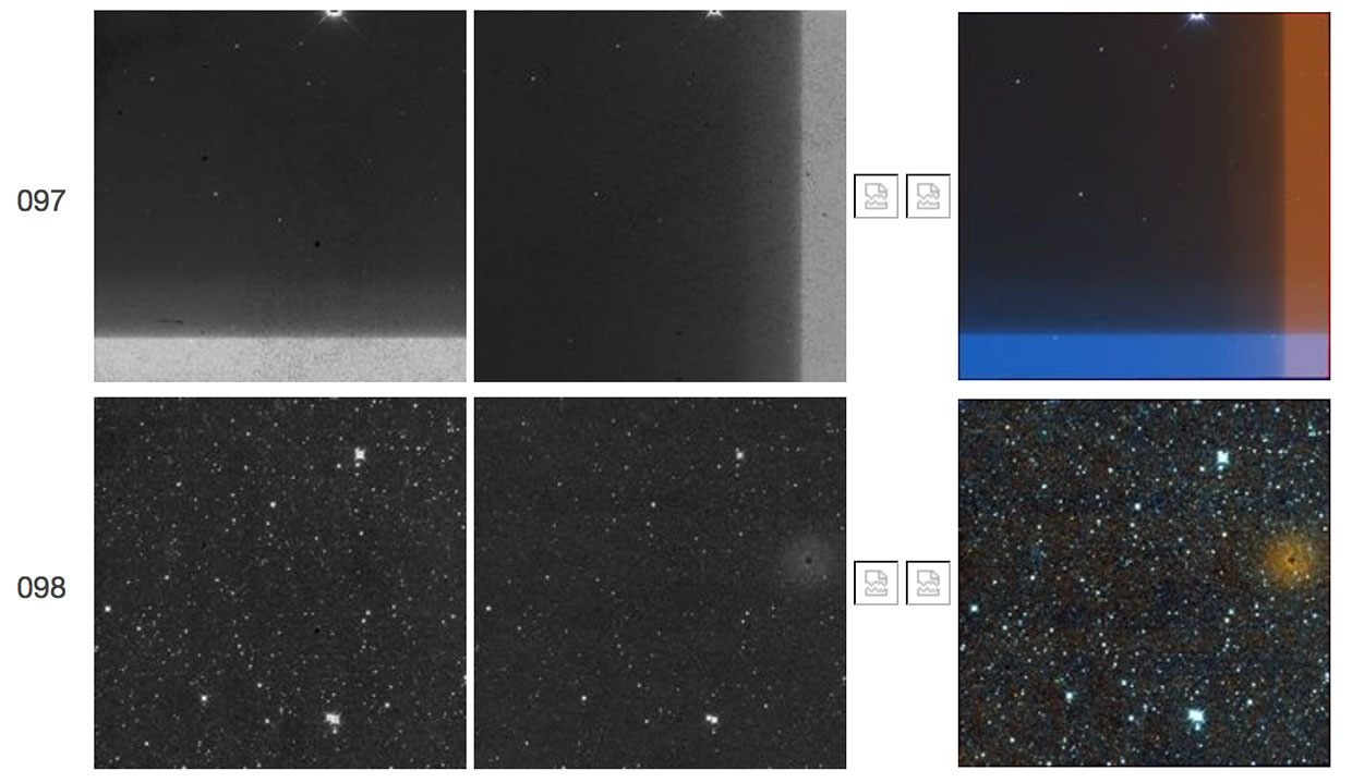 |
| Figure 7 - Scan 67842b, framesets 097-098. Frameset 097 exhibits a "TV test pattern". Frameset 098 shows a weak W2 resonant pixel halo. |
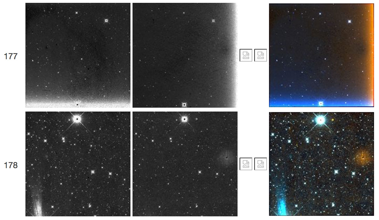 |
| Figure 8 - Scan 70877b, framesets 177-178. Frameset 177 exhibits a "TV test pattern," and frameset 178 shows a weak W2 resonant pixel halo. The W1 counterpart of the W2 resonant pixel halo is also seen here. |
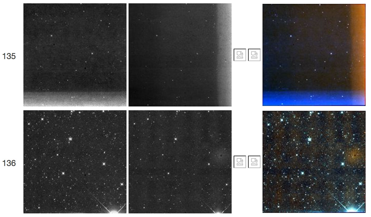 |
| Figure 9 - Scan 73648a, framesets 135-136. Like Figures 7 and 8 above, the first frameset shows a "TV test pattern" followed in the second frameset by a weak W2 resonant pixel halo. |
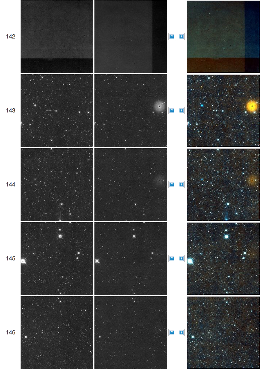 |
| Figure 10 - Scan 77064a, framesets 142-146. The first frameset shows a "TV test pattern" followed in subsequent framesets by a W2 resonant pixel halo. The W1 counterpart of the W2 resonant pixel halo is also seen here. |
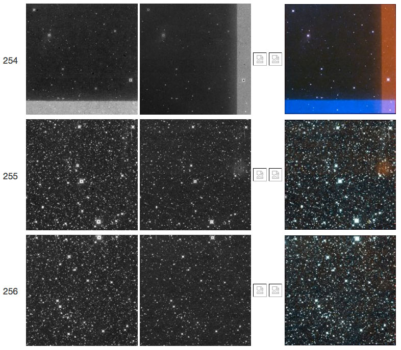 |
| Figure 11 - Scan 77978a, framesets 254-256. The first frameset shows a "TV test pattern" followed in subsequent framesets by a W2 resonant pixel halo. |
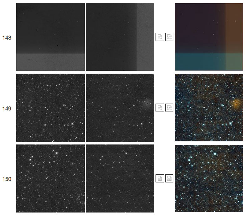 |
| Figure 12 - Scan 78569a, framesets 148-150. The first frameset shows a "TV test pattern" followed in subsequent framesets by a W2 resonant pixel halo. The W1 counterpart of the W2 resonant pixel halo is also seen here. |
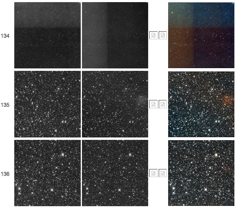 |
| Figure 13 - Scan 79980a, framesets 134-136. The first frameset shows a "TV test pattern" followed in subsequent framesets by a W2 resonant pixel halo. |
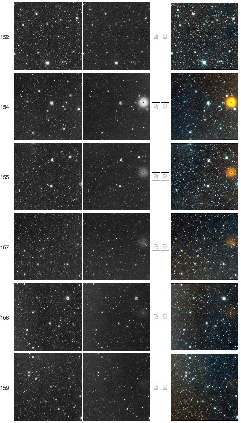 |
| Figure 14 - Scan 80992a, framesets 152-159. Frameset 153, where a "TV test pattern" would be seen, failed processing. It is followed in subsequent framesets by a W2 resonant pixel halo. The W1 counterpart of the W2 resonant pixel halo is also seen here. |
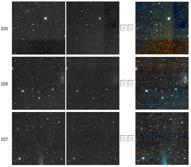 |
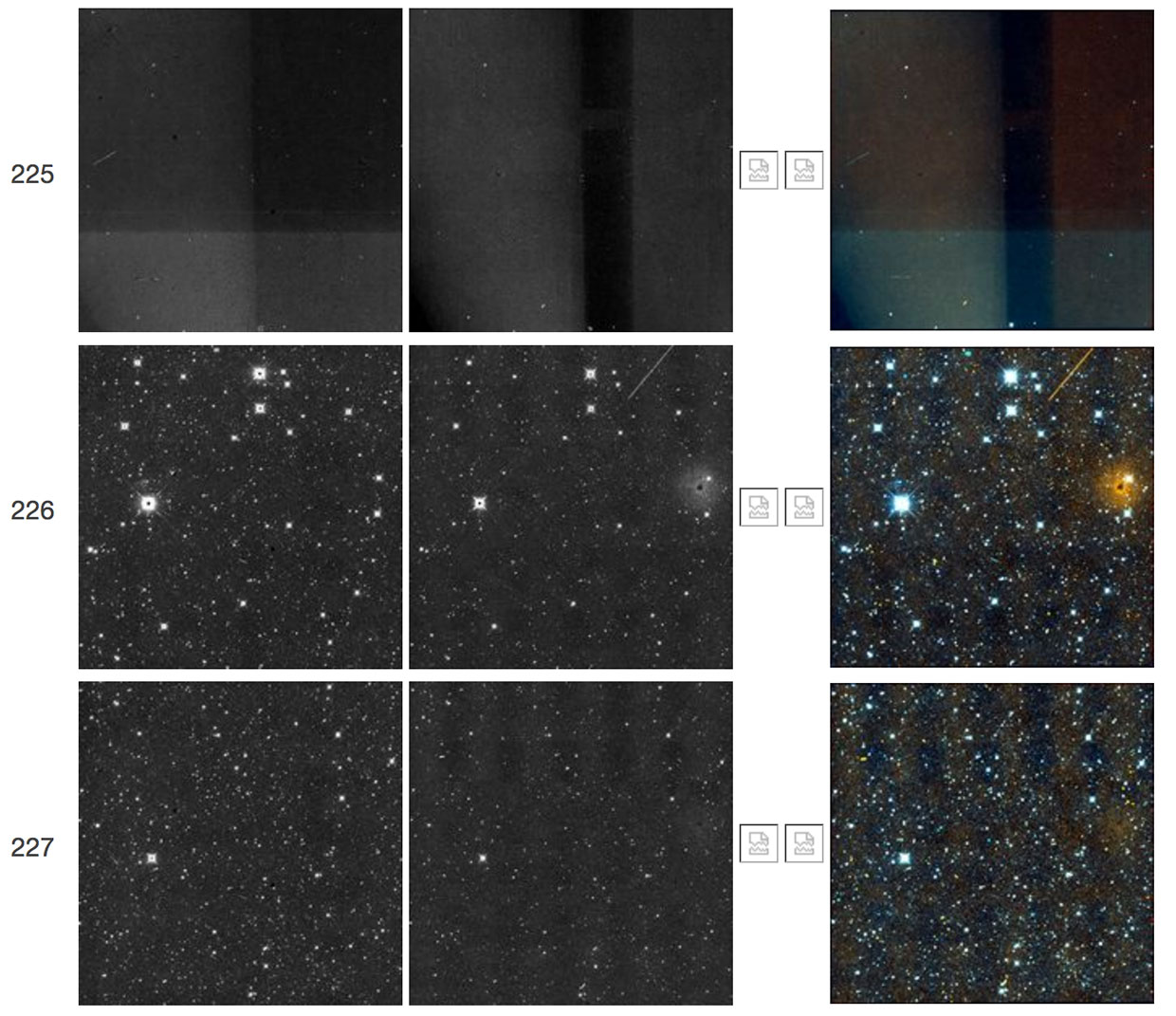
| Figure 15 - Scan 81074a, framesets 225-227. The first frameset shows a "TV test pattern" followed in subsequent framesets by a W2 resonant pixel halo. The diffuse, double-lobed blue feature in frameset 226, coincidentally near the resonant pixel, is the galaxy IC 2574, also known as Coddington's Nebula. |
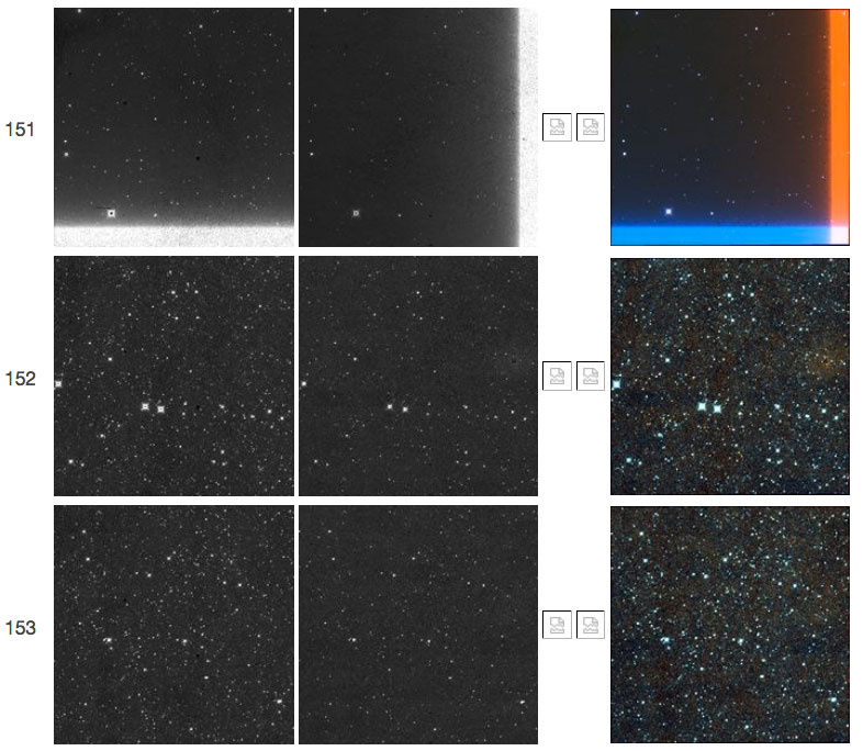 |
| Figure 16 - Scan 82157b, framesets 151-153. The first frameset shows a "TV test pattern" followed in subsequent framesets by a W2 resonant pixel halo. |
 |
| Figure 17 - Scan 84826a, framesets 146-148. The first frameset shows a "TV test pattern" followed in subsequent framesets by a W2 resonant pixel halo. |
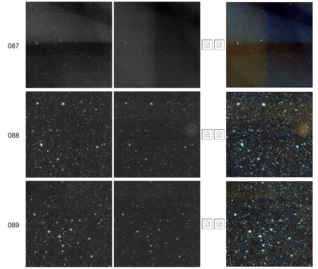 |
| Figure 18 - Scan 86714a, framesets 087-089. The first frameset shows a "TV test pattern" followed in the next two framesets by a W2 resonant pixel halo. The W1 counterpart of the W2 resonant pixel halo is also seen here. |
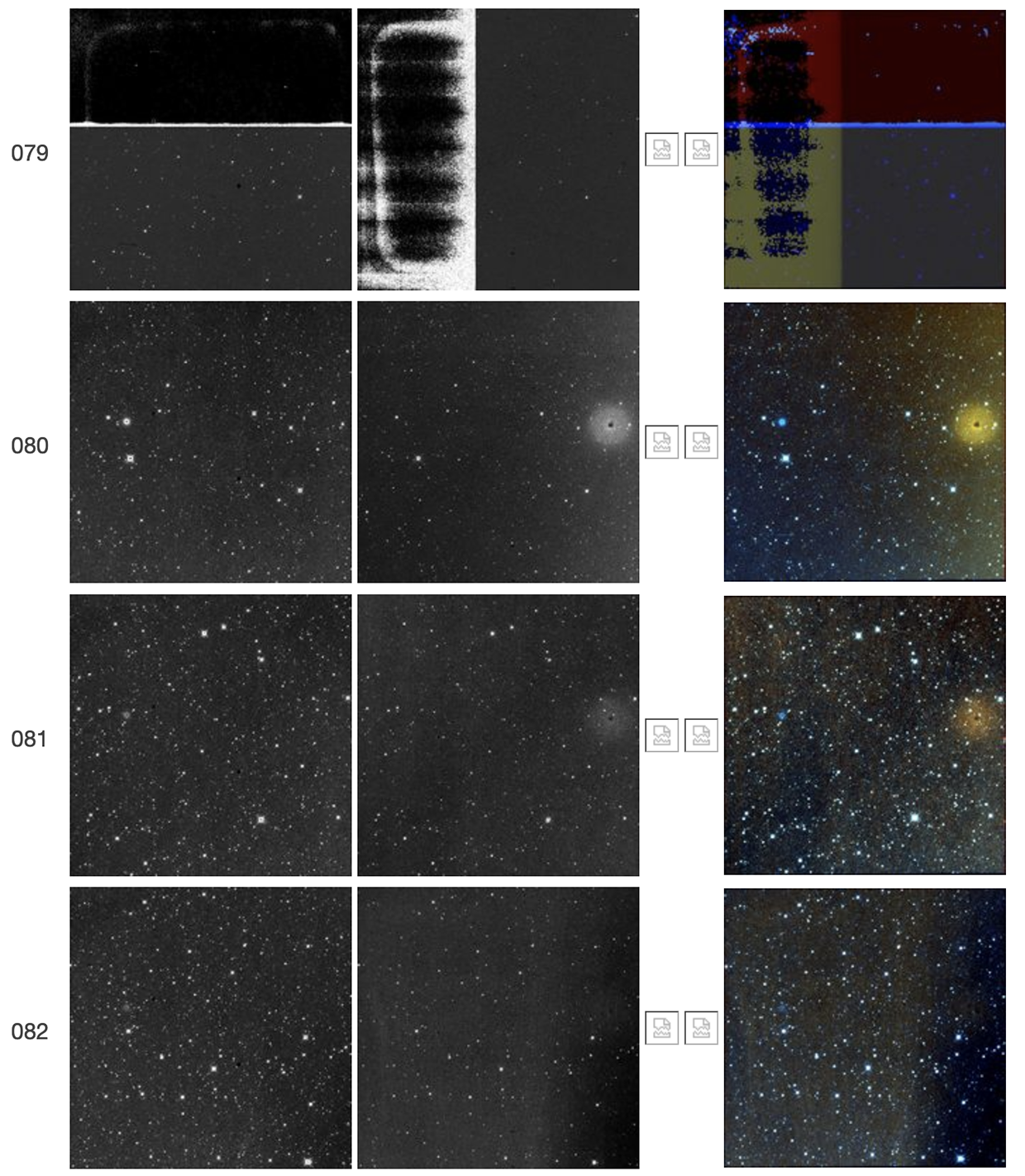 |
| Figure 19 - Scan 87458a, framesets 079-082. The first frameset shows a "TV test pattern" and unusual illumination patterns caused in part by saturation. Framesets 080 and 081 show a decaying W2 resonant pixel halo, which is no longer discernible in 082. All of these framesets show elevated backgrounds from a very bright object off the arrays. The W1 counterpart of the W2 resonant pixel halo is also seen here. |
 |
| Figure 20 - Scan 87990a, framesets 023-026. The first frameset shows a "TV test pattern" followed in subsequent framesets by a W2 resonant pixel halo. The W1 counterpart of the W2 resonant pixel halo is also seen here. |
 |
| Figure 21 - Scan 91539a, framesets 187-188. The first frameset shows a "TV test pattern" followed in the subsequent frameset by a W2 resonant pixel halo. |
 |
| Figure 22 - Scan 93691a, framesets 014-015. The first frameset shows a "TV test pattern" followed in the subsequent frameset by a weak W2 resonant pixel halo. The latter can be seen more convincingly in Figure 22a below. |
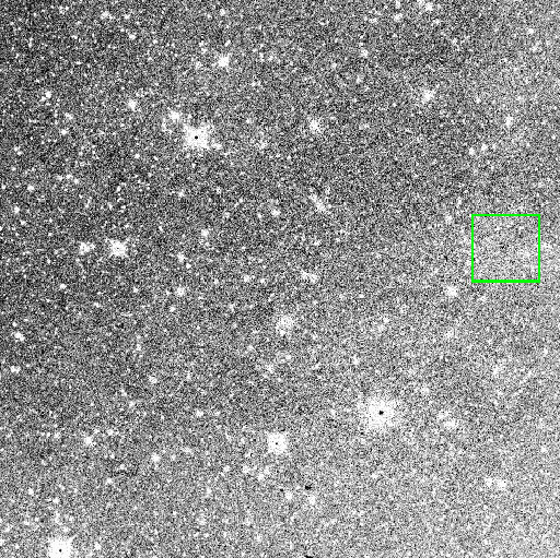 |
| Figure 22a - Scan 93691a, frameset 015. The weak resonant pixel halo in Figure 22 is also shown here, in the W2 frame, after heavily stretching the image scale. The green box is centered at the coordinates of the halo. |
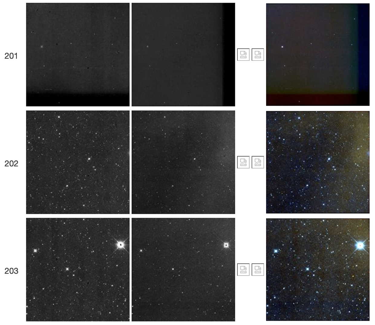 |
| Figure 23 - Scan 93703a, framesets 201-203. Frameset 201 exhibits a "TV test pattern," and frameset 202 shows a weak W2 resonant pixel halo, which is no longer discernible in 203. All of these framesets also show elevated backgrounds at least partly due to Moonglow. |
 |
| Figure 24 - Scan 94036a, framesets 115-120. Frameset 115 has high backgrounds and an unusual illumination pattern caused in part by saturation. This frameset also failed to complete processing, so its color-composite image is not available. Framesets 116-120 show a W2 resonant pixel halo. The W1 counterpart of the W2 resonant pixel halo is also seen here. |
 |
| Figure 25 - Scan 94908a, framesets 038-039. The first frameset shows a "TV test pattern" followed in frameset 039 by a weak W2 resonant pixel halo. Frameset 039 also shows a curious small W2-only (red) feature, near the center. It resembles a latent, but no astrophysical object is found in preceding framesets. Its asymmetric shape also resembles that of an optical ghost. |
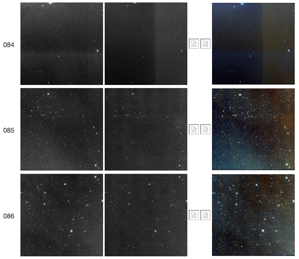 |
| Figure 26 - Scan 99104a, framesets 084-086. The first frameset shows a "TV test pattern" followed in the subsequent frameset by a weak W2 resonant pixel halo, which is no longer discernible in 086. All of these framesets show elevated backgrounds from a very bright object off the arrays. |
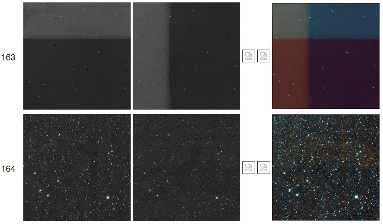 |
| Figure 27 - Scan 05442r, framesets 163-164. The first frameset shows a "TV test pattern" followed in the second frameset by a very weak W2 resonant pixel halo that is more obvious in a hard stretch of the FITS image. |
 |
| Figure 28 - Scan 05932r, framesets 045-047. The first frameset shows a "TV test pattern" followed in the second frameset by a very weak W2 resonant pixel halo. |
 |
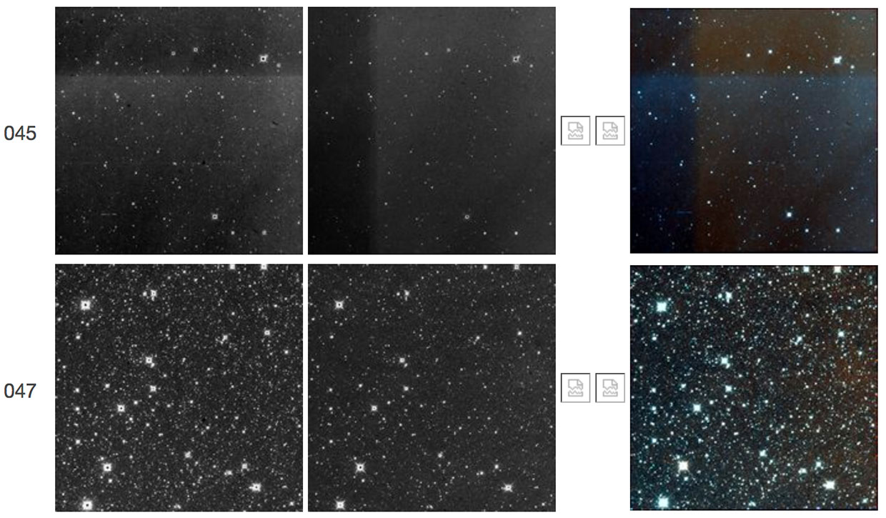
| Figure 29 - Scan 10546r, framesets 142-150. In this sequence, frameset 143 (not shown) was completely saturated in both bands in what the raw images confirm was an unusually bright "TV test pattern" phenomenon. This frameset failed processing. Subsequent framesets 145-150 show a slowly decaying resonant pixel halo in W2. The W1 counterpart of the W2 resonant pixel halo is also seen here. |
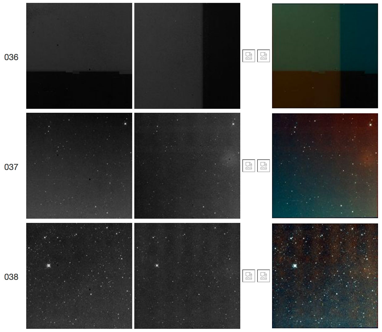 |
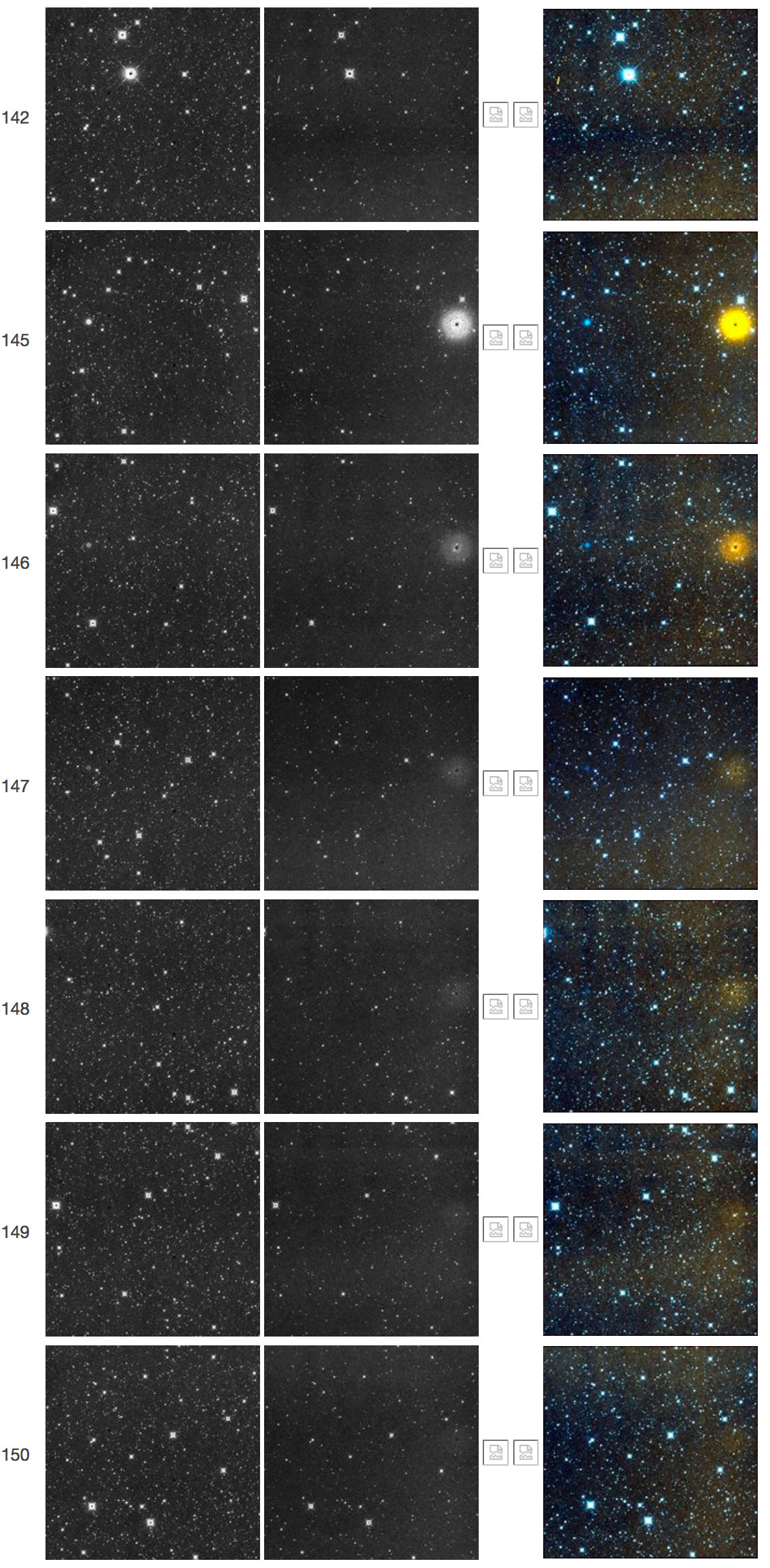
| Figure 30 - Scan 11960r, framesets 036-038. The first frameset shows a "TV test pattern" followed in the next two framesets by a decaying W2 resonant pixel halo. |
 |
| Figure 31 - Scan 27520r, framesets 225-227. The first frameset shows a "TV test pattern" followed in the next two framesets by a decaying W2 resonant pixel halo. The TV test pattern is unusual in that the W2 frameset shows a vertical rectangular area of lower signal in the middle of the array, instead of at one of the edges. |
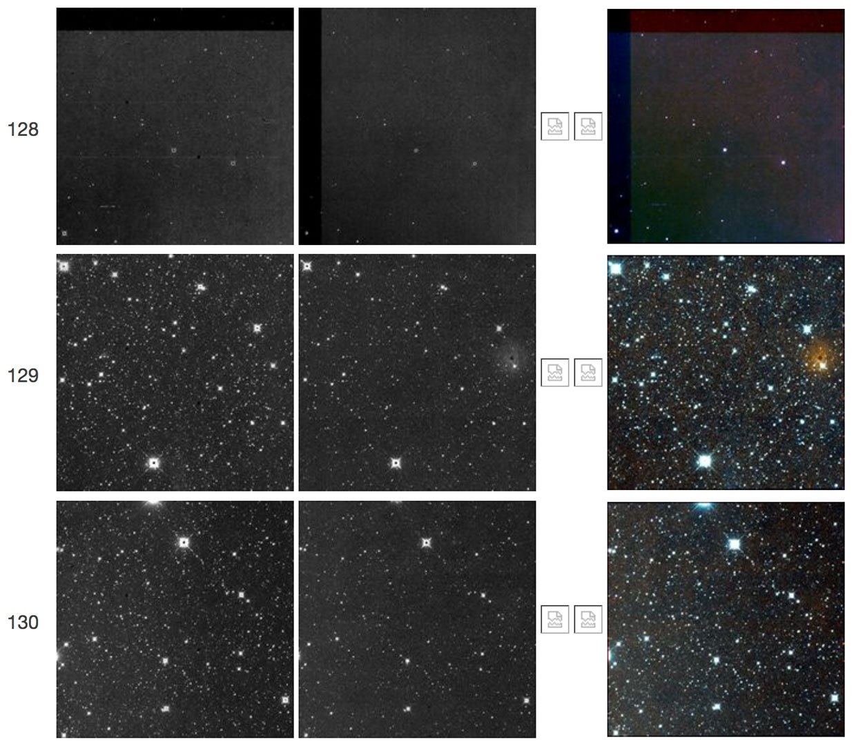 |
| Figure 32 - Scan 27578r, framesets 128-130. The first frameset shows a "TV test pattern" followed in the next frameset by a decaying W2 resonant pixel halo, which is no longer discernible in frameset 130. |
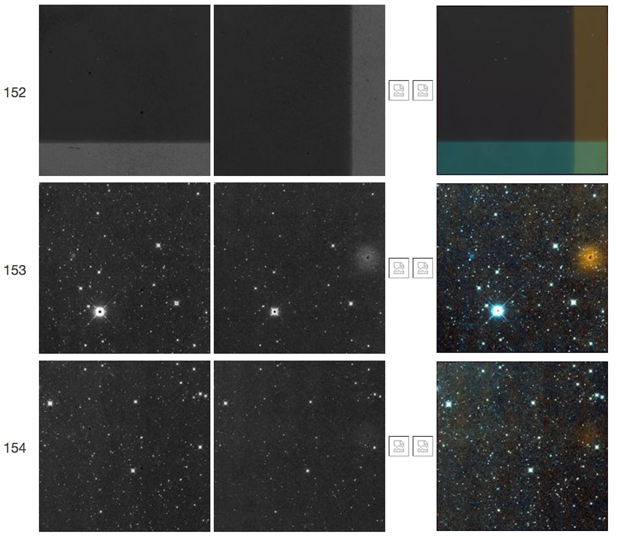 |
| Figure 33 - Scan 28226r, framesets 152-154. The first frameset shows a "TV test pattern" followed in the next two framesets by a decaying W2 resonant pixel halo. The W1 counterpart of the W2 resonant pixel halo is also seen here. |
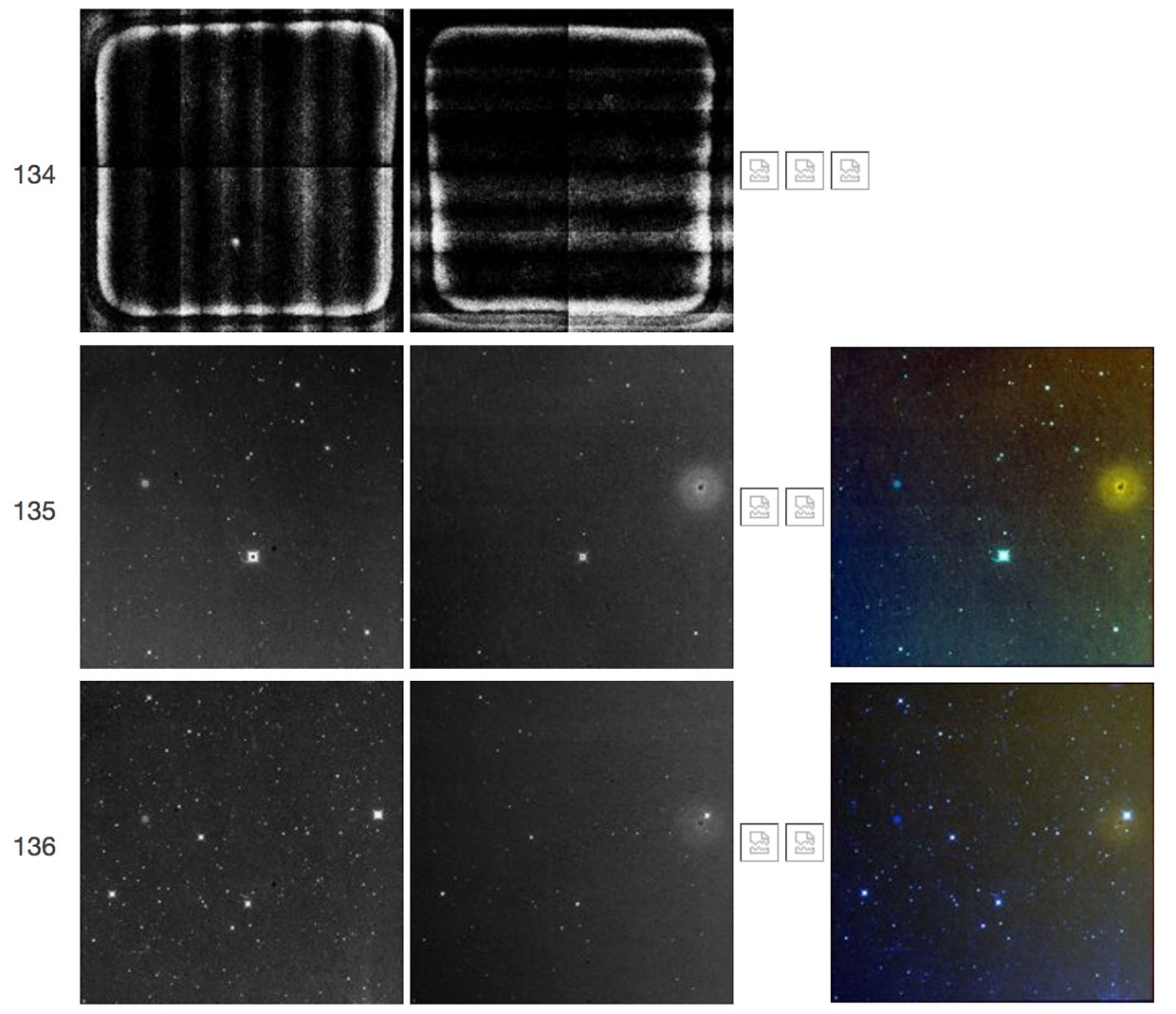 |
| Figure 34 - Scan 29492r, framesets 134-136. Frameset 134 has high backgrounds and an unusual illumination pattern caused in part by saturation. This frameset also failed to complete processing, so its color-composite image is not available. Framesets 135-136 show a W2 resonant pixel halo. The W1 counterpart of the W2 resonant pixel halo is also seen here. |
 |
| Figure 35 - Scan 33862r, framesets 139-142. The first frameset shows a "TV test pattern" followed in the next two framesets by a decaying W2 resonant pixel halo. The W1 counterpart of the W2 resonant pixel halo is also seen here. |
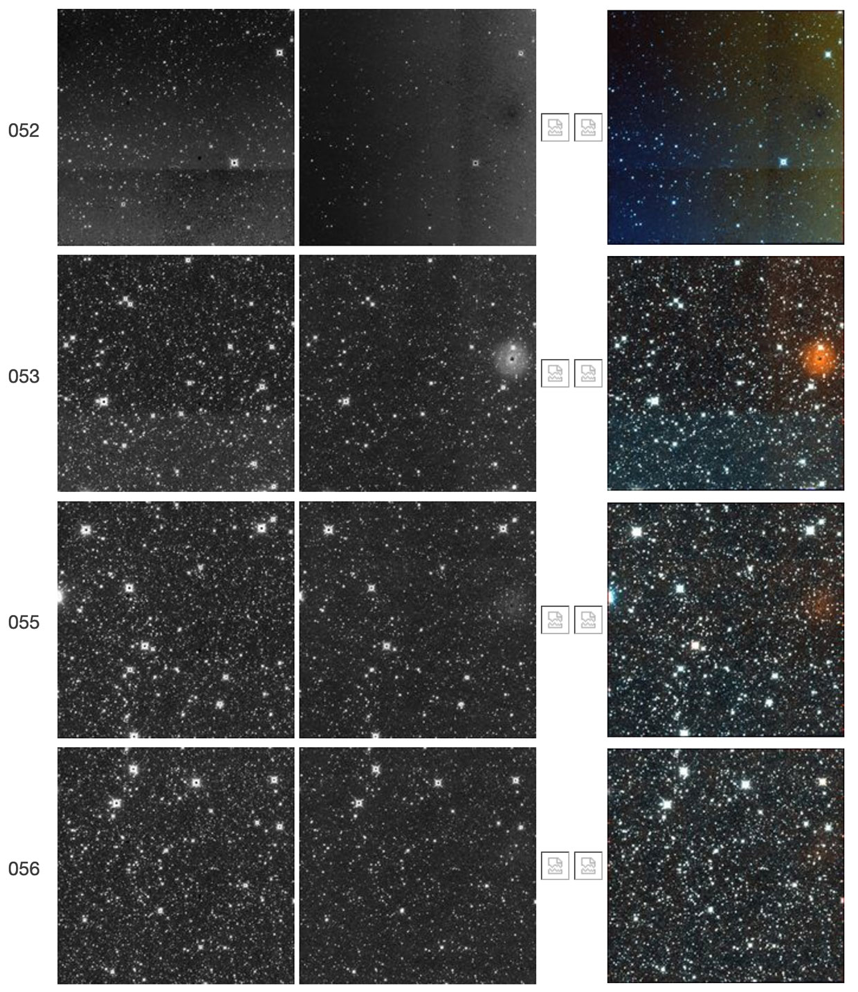 |
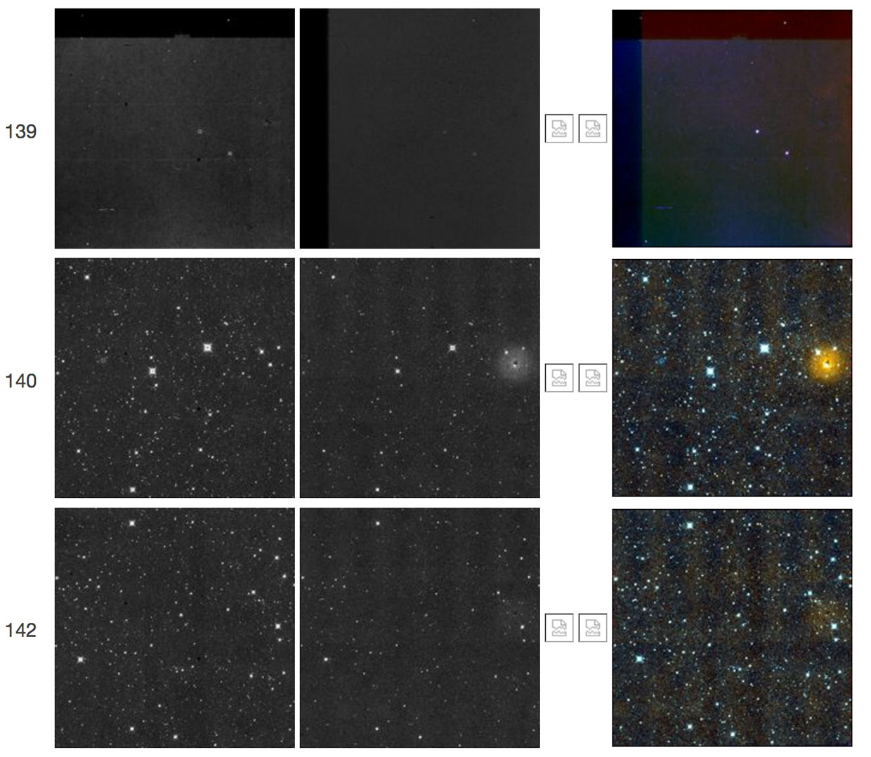
| Figure 36 - Scan 37872r, framesets 052-056. The first frameset shows a "TV test pattern" followed in the next three framesets by a decaying W2 resonant pixel halo. The first frameset itself is unusual because it exhibits a negative or reverse halo around the W2 resonant pixel area. The TV test pattern also lacks a sharp jump in the backgrounds but instead shows a generally smooth gradient in addition to the jump itself. |
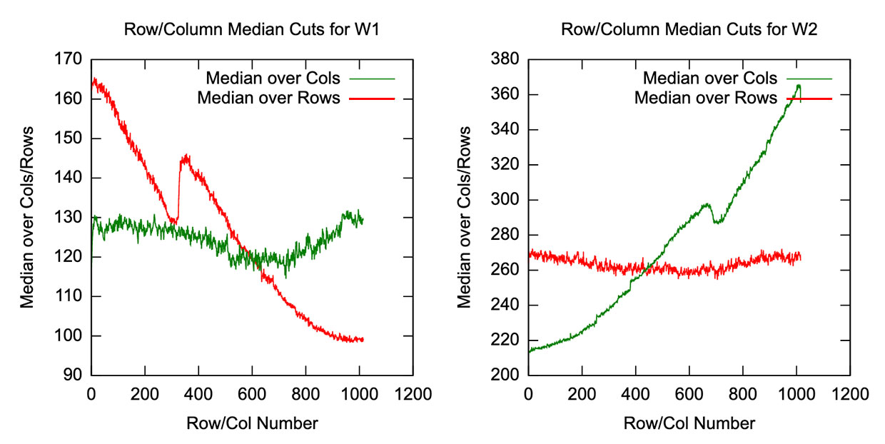 |
| Figure 36a - Scan 37872r, frameset 052. Signal medians over columns and over rows are shown for the W1 (left panel) and W2 (right panel) arrays described in Figure 36, above. The left panel shows that the median row signal in W1 (red line) drops gradually from the bottom of the array to the top, with a 15 DN jump partway through. The right panel shows that the median column signal in W2 (green line) rises gradually towards the right side of the array, with a 10 DN jump partway through. |
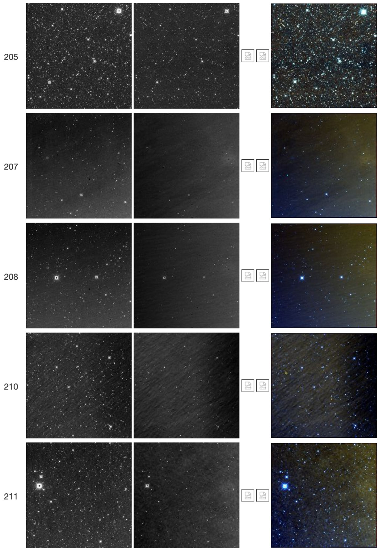 |
| Figure 37 - Scan 37942r, framesets 205-211. A very extreme "TV test pattern" was present in frameset 206, but the frameset is not shown because its almost total saturation caused it to fail processing. Glow patterns and a hint of the W2 resonant pixel halo are seen in framesets 207-211. The W1 counterpart of the W2 resonant pixel halo is also seen here. |
 |
| Figure 38 - Scan 39449r, framesets 065-067. The first frameset shows a "TV test pattern" followed in the next frameset by a decaying W2 resonant pixel halo, which is no longer visible in frameset 067. |
 |
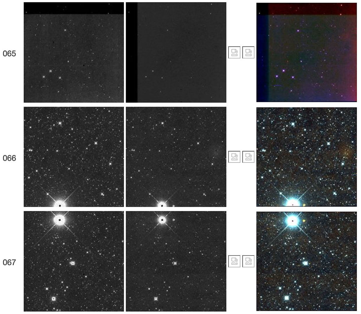
| Figure 39 - Scan 43962r, framesets 092-096. Frameset 093 shows a "TV test pattern" followed in the next frameset by a decaying W2 resonant pixel halo, which is no longer visible in frameset 096. Frameset 093 also shows at least three wedge-like or propeller-like features. The W1 counterpart of the W2 resonant pixel halo is also seen here. |
 |
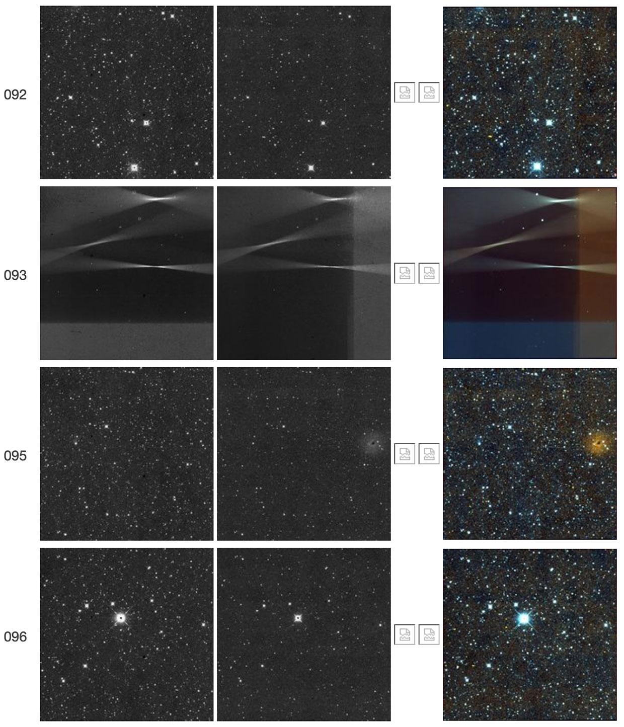
| Figure 40 - Scan 44657r, framesets 183-188. The first frameset (183) shows a "TV test pattern" followed in the next four framesets by a decaying W2 resonant pixel halo. The second frameset (184) shows an unusual latent of the TV test pattern itself, in addition to the resonant pixel halo. The W1 counterpart of the W2 resonant pixel halo is also seen here. |
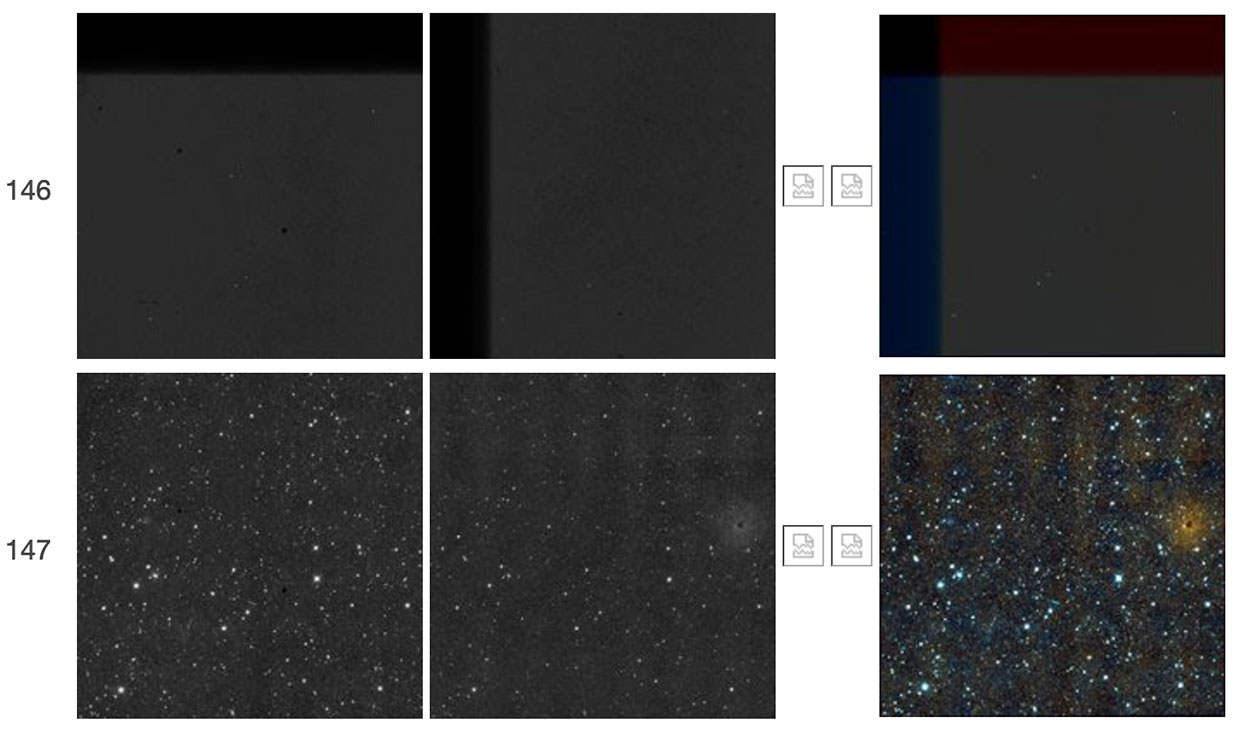 |
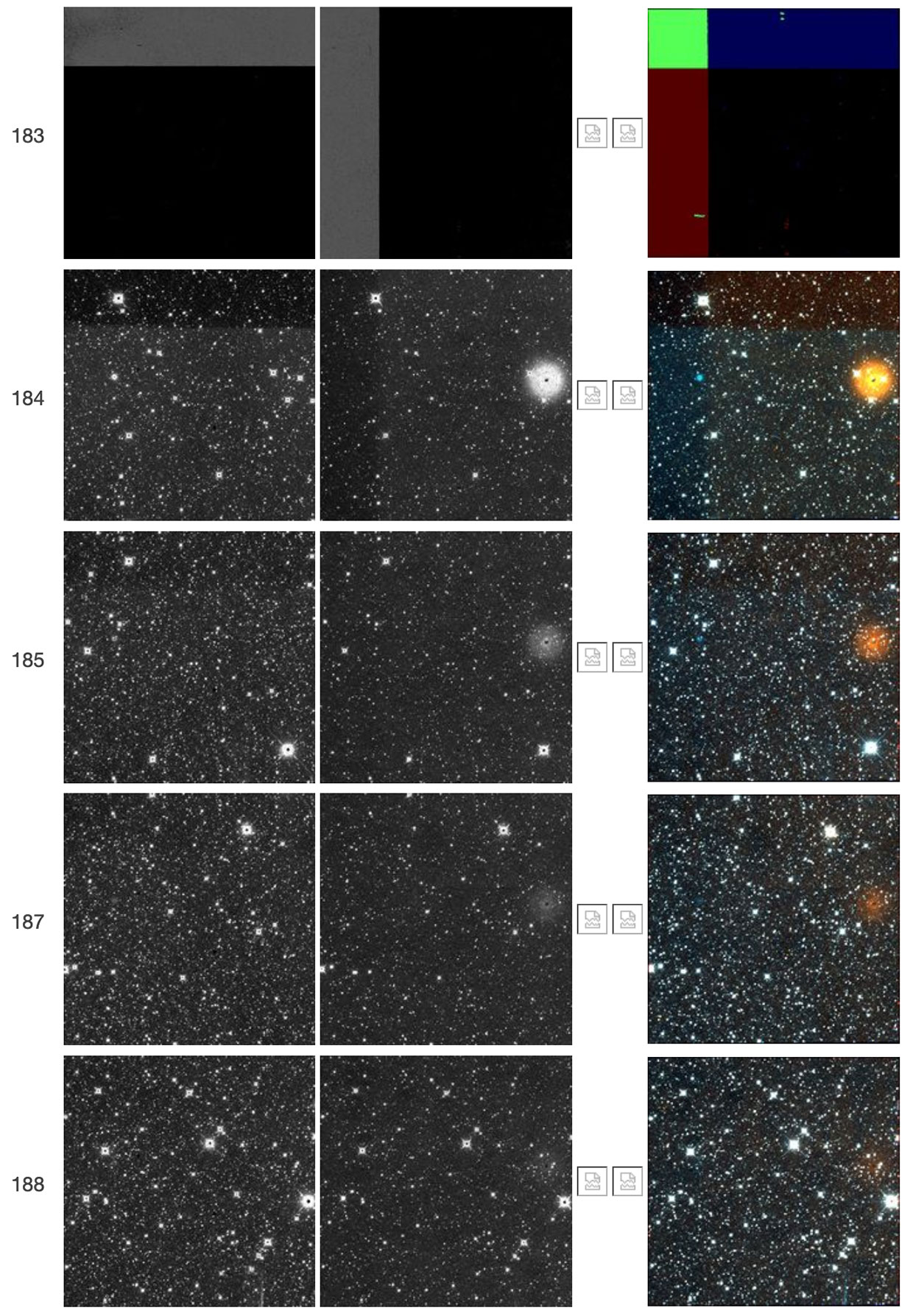
| Figure 41 - Scan 50265r, framesets 146-147. The first frameset shows a "TV test pattern" followed in the subsequent frameset by a W2 resonant pixel halo. The W1 counterpart of the W2 resonant pixel halo is also seen here. |
 |
| Figure 42 - Scan 50396r, framesets 157-159. The first frameset shows a "TV test pattern" followed in the next two framesets by a decaying W2 resonant pixel halo. The TV test pattern lacks a sharp jump in the backgrounds but instead shows a generally smooth gradient. The W1 counterpart of the W2 resonant pixel halo is also seen here. |
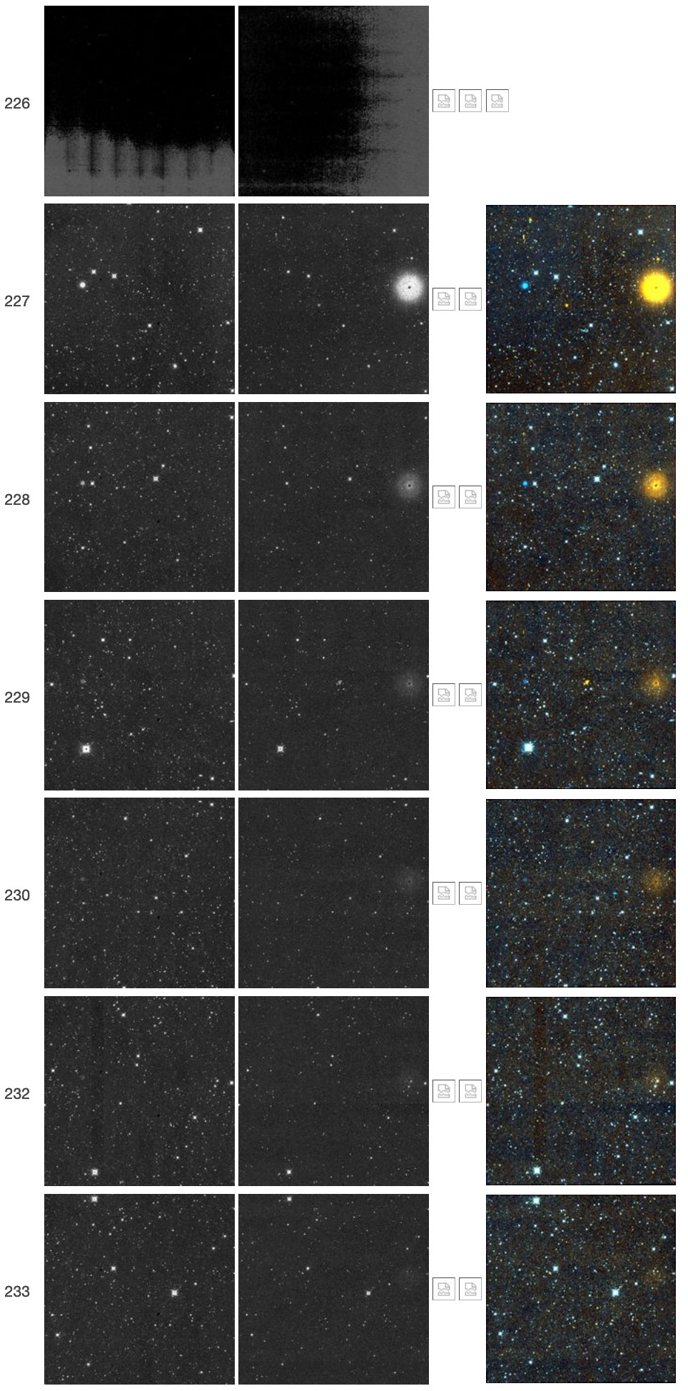 |
| Figure 43 - Scan 51630r, framesets 226-233. Frameset 226 has high backgrounds and an unusual illumination pattern caused in part by saturation. This frameset also failed to complete processing, so its color-composite image is not available. Framesets 227-233 show the decay of the W2 resonant pixel halo. The W1 counterpart of the W2 resonant pixel halo is also seen here. |
 |
| Figure 44 - Scan 52920r, framesets 151-152. The first frameset shows a "TV test pattern" followed in the subsequent frameset by a W2 resonant pixel halo. The W1 counterpart of the W2 resonant pixel halo is also seen here. |
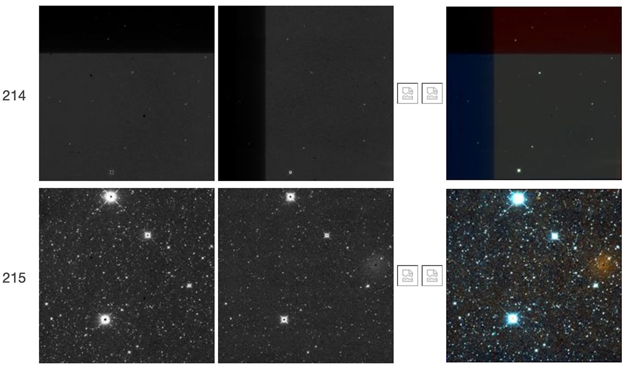 |
| Figure 45 - Scan 53461r, framesets 214-215. The first frameset shows a "TV test pattern" followed in the subsequent frameset by a W2 resonant pixel halo. The W1 counterpart of the W2 resonant pixel halo is also seen here. |
 |
| Figure 46 - Scan 56724r, framesets 105-106. The first frameset shows a "TV test pattern" followed in the subsequent frameset by a W2 resonant pixel halo. The W1 counterpart of the W2 resonant pixel halo is also seen here. |
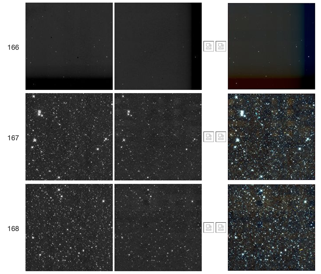 |
| Figure 47 - Scan 57193r, framesets 166-168. The first frameset shows a "TV test pattern" followed in the subsequent frameset by a very weak W2 resonant pixel halo, which is no longer discernible in 168. |
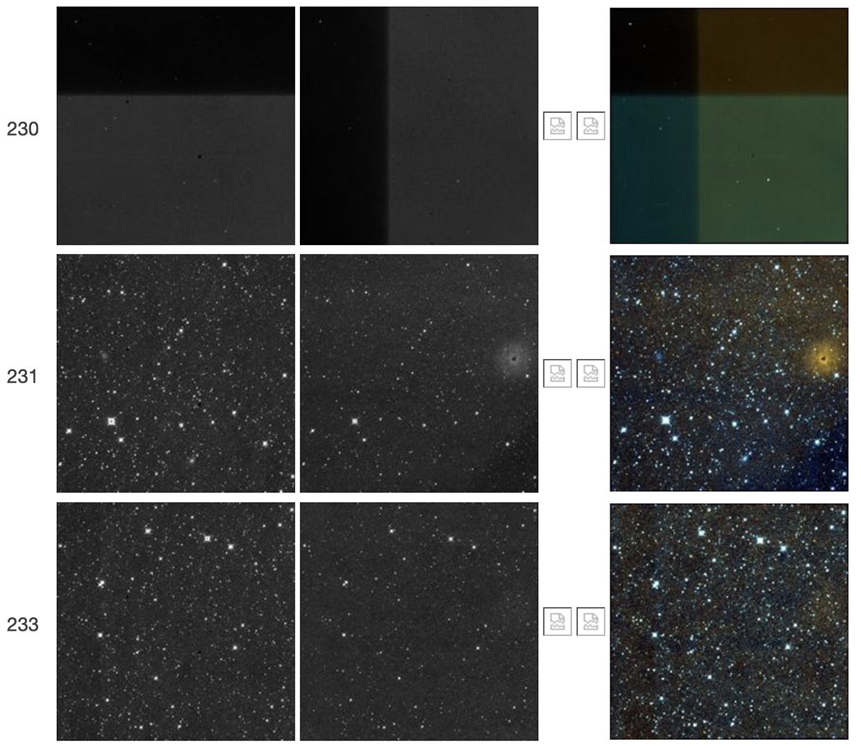 |
| Figure 48 - Scan 59911r, framesets 230-233. The first frameset shows a "TV test pattern" followed in the next two framesets by a decaying W2 resonant pixel halo. The W1 counterpart of the W2 resonant pixel halo is also seen here. |
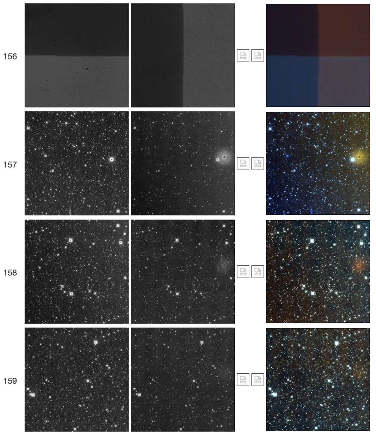 |
| Figure 49 - Scan 60368r, framesets 156-159. The first frameset shows a "TV test pattern" followed in the next three framesets by a decaying W2 resonant pixel halo. The W1 counterpart of the W2 resonant pixel halo is also seen here. |
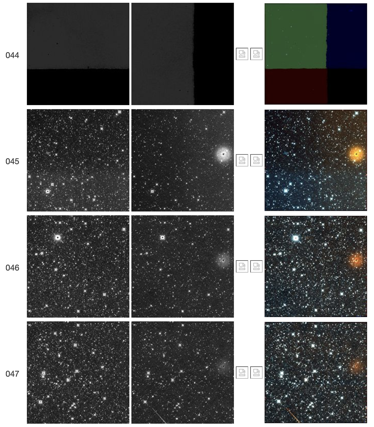 |
| Figure 50 - Scan 60384r, framesets 044-047. The first frameset shows a "TV test pattern" followed in the next three framesets by a decaying W2 resonant pixel halo. The W1 counterpart of the W2 resonant pixel halo is also seen here. |
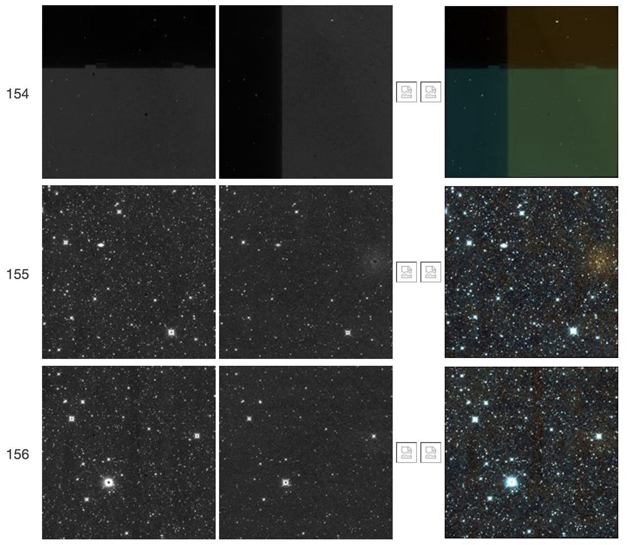 |
| Figure 51 - Scan 61094r, framesets 154-156. The first frameset shows a "TV test pattern" followed in the next two framesets by a decaying W2 resonant pixel halo. The W1 counterpart of the W2 resonant pixel halo is also seen here. |
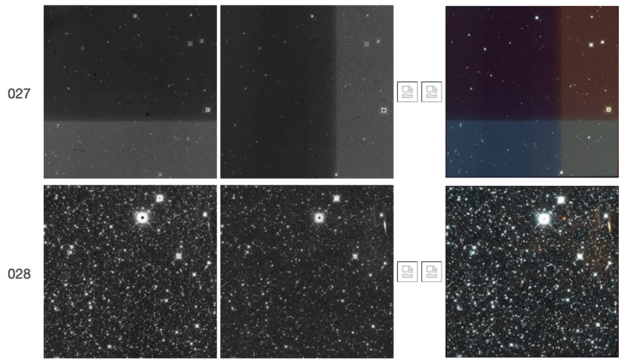 |
| Figure 52 - Scan 62217r, framesets 027-028. The first frameset shows a "TV test pattern" followed in the next frameset by a weak W2 resonant pixel halo. |
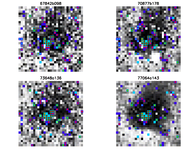
Figures 53 and 54 show 31×31 pixel cut-outs centered at the nominal resonant pixel, for each of the first framesets in Figures 1-10 that show the feature. These cut-outs are shown in the two Figures 53 and 54, instead of a single figure, for clarity. The resonant pixel seems to have very low responsivity, but is also transient. Pixels in its vicinity are also transient, are excessively noisy, or have very low responsivity. Note that dead pixels have constant signal at the digital saturation level. The figures show that the nominal resonant pixel itself is not unique but more likely is a member of a tight cluster of masked pixels. Color coding on the figures is explained in the legend below:
Table 1: Color Coding of Masked Pixels
|
|
Excessively noisy, or known broken hardware. Static mask |
|
|
Dead, or low responsivity or low dark current. Static mask |
|
|
High dark current or responsivity, or saturated at any sample, or uncertain non-linearity. Static mask |
|
|
Broken pixel, or negative slope fit. Dynamic mask |
|
|
Saturated at any sample. Dynamic mask |
|
|
Transient, or unreliable non-linearity, or spike outlier. Dynamic mask |
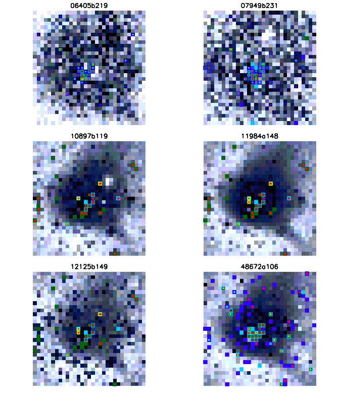 |
| Figure 53 - Zoom-ins centered at the resonant pixel feature from Figures 1-6. See Table 1 for an explanation of the color coding of masked pixels. |
 |
| Figure 54 - Zoom-ins centered at the resonant pixel feature from Figures 7-10. See Table 1 for an explanation of the color coding of masked pixels. |
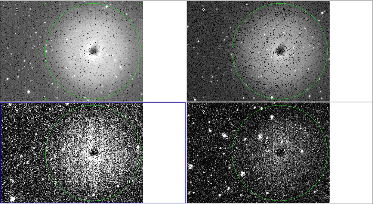
It has been observed that bright objects falling near the right edge of the W2 array tend to produce longer-lasting latents than bright objects falling elsewhere, as discussed in IV.4.g.iv.1.e. Figure 55 shows an example of this effect. The bright satellite trail in this figure leaves a W2 latent but only in the vicinity of the resonant pixel. Figures 56 and 57 show similar instances where brighter satellite trails leave W2 latents in the subsequent three or four framesets, but markedly brighter at the resonant pixel position. That the resonant pixel falls within this region, where bright stars and satellite trails leave more prominent latents than elsewhere in the array, suggests that the two effects may be related. This point is further illustrated in Figures 58 and 59, which are zoomed versions of satellite trails and of the resonant pixel.
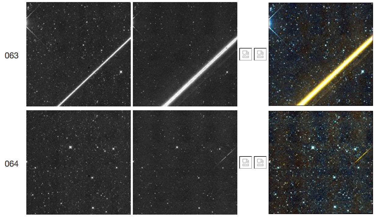 |
| Figure 55 - Scan 77602a, frameset 063, exhibits a satellite trail that coincidentally crossed the W2 resonant pixel. The corresponding latent in the subsequent frameset, 064, is brightest in the region of the W2 resonant pixel. |
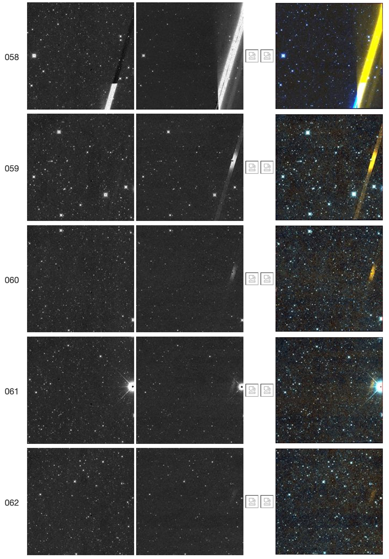 |
| Figure 56 - Scan 57227r, framesets 058-062. The bright satellite trail in frameset 058 leaves W2 latents in framesets 059-062. These latents are pronouncedly brighter at the position of the W2 resonant pixel, thus further suggesting that the latter is related to the phenomenon of longer-duration short-term latents in this region of the array. |
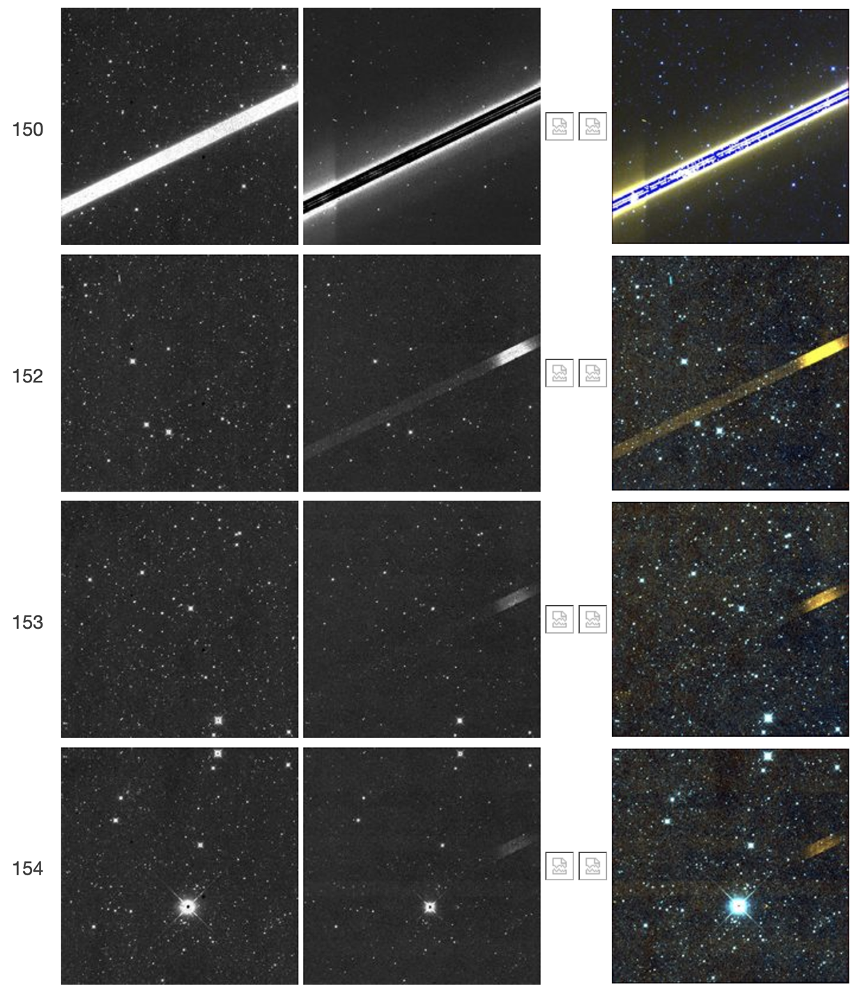 |
| Figure 57 - Scan 61073r, framesets 150-154. This is another example of a bright satellite trail, in this case in frameset 150, that coincidentally crosses the W2 resonant pixel. It leaves W2 latents in framesets 152-154, which, as in the case of Figures 55 and 56, are pronouncedly brighter at the position of the W2 resonant pixel. This example further suggests that the W2 resonant pixel is related to the phenomenon of longer-duration short-term latents in this region of the array. |
 |
| Figure 58 - Zoomed illustration of four of the resonant pixels from Figures 1-10. The 100-pixel radius circles are centered on each instance of the resonant pixel. Compare this to the long-term latent positions shown in Figure 59, below. |
 |
| Figure 59 - Zoomed illustration in W2 of two satellite trails that coincidentally crossed the resonant pixel. The left panel is from frameset 70774a164, and the right panel is 77602a063, also illustrated in Figure 55. The 100-pixel radius circles are centered on the resonant pixel, as in Figure 58. |
We looked for a correlation between the intensity of the resonant pixel feature, and the signal in the illuminated frameset preceding it. To this end, we carried out aperture photometry with the ATV tool in IDL, centered at the nominal resonant pixel position, and using the radii for aperture and sky annuli illustrated in Figure 60. We separately calculated the centroid of the feature, via its first moment of inertia, and found out that it is reasonably constant, except for the faintest examples that are affected by noise.
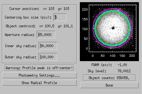 |
| Figure 60 - GUI for ATV photometry centered at the resonant pixel position, illustrated for frameset 148 in scan 11984a. |
Table 2 lists our measurements for all the fifty-two instances of the resonant pixel. We obtained the mean signal of the illuminated W2 frame (the one for which the frameset often shows a "TV test pattern"), except for the framesets in Figures 1, 2, 4, 6, 14, 24, 29, 34, 37, and 43 for which there were no level-1b data available for the illuminated W2 frame. In cases where a TV test pattern was discernible, we also measured the W2 signal jump between the elevated region and the rest of the array. Figure 61 illustrates an example estimate of signal jump in a TV test pattern. We also measured the signal at the top of either the TV test pattern (row cut in the right-hand-side panel of Figure 61) or the maximum signal of the illuminated W2 frame. We also measure aperture photometry of the resonant pixel feature, except for the framesets in Figures 9, 16, 26, 30, 34, 37, 38, 50, and 52 for which this feature is either too faint (in most cases), or is contaminated by sources or cosmic rays (such as in the case of Figures 50 and 52).
Table 2: Measured Signal in the Resonant Pixel Halo and in the Preceding Frame
|
Figure |
Aperture Photometry of Resonant Pixel (DN) |
Mean Signal In Preceding Illuminated W2 Frame (DN) |
W2 Signal Jump In TV Test pattern (if visible) (DN) |
Maximum Signal In Preceding Illuminated W2 Frame (DN) |
Resonant "Pixel" Feature Centroid (pix) |
|
1 |
430,132 |
N/A |
N/A |
N/A |
[912.7, 567.3] |
|
2 |
80,263 |
N/A |
N/A |
N/A |
[912.7, 567.3] |
|
3 |
647,687 |
224.6 |
6,300 |
7,500 |
[911.9, 567.5] |
|
4 |
936,058 |
N/A |
N/A |
N/A |
[912.2, 567.7] |
|
5 |
241,604 |
10,982 |
N/A |
11,500 |
[912.3, 567.5] |
|
6 |
634,134 |
N/A |
N/A |
N/A |
[912.5, 567.4] |
|
7 |
64,177 |
401.9 |
900 |
1,200 |
[912.4, 567.2] |
|
8 |
99,804 |
96.88 |
230 |
380 |
[912.3, 567.1] |
|
9 |
< 0 |
1,324 |
400 |
1,800 |
[912.0, 567.0] |
|
10 |
267,156 |
11,050 |
1,300 |
11,300 |
[911.6, 563.7] |
|
11 |
258,044 |
2,527 |
700 |
3,100 |
[914.0, 556.7] |
|
12 |
48,953 |
532.6 |
1,200 |
1,400 |
[908.6, 564.5] |
|
13 |
200,573 |
5,128 |
300 |
5,400 |
[912.3, 566.0] |
|
14 |
698,415 |
N/A |
N/A |
N/A |
[912.9, 568.8] |
|
15 |
41,645 |
50.6 |
10 |
50 |
[912.9, 567.2] |
|
16 |
< 0 |
144.6 |
460 |
575 |
[911.9, 567.1] |
|
17 |
150,387 |
900 |
1,200 |
1,450 |
[911.2, 567.2] |
|
18 |
80,692 |
2,929 |
280 |
2,750 |
[912.3, 567.4] |
|
19 |
276,330 |
2,391 |
7,790 |
7,800 |
[913.2, 567.4] |
|
20 |
148,969 |
448 |
2,050 |
2,200 |
[912.6, 567.0] |
|
21 |
111,000 |
739 |
900 |
1,250 |
[912.2, 566.2] |
|
22 |
49,065 |
730 |
815 |
875 |
[908.4, 564.0] |
|
23 |
80,731 |
1,878 |
800 |
2,000 |
[913.4, 567.4] |
|
24 |
852,538 |
N/A |
N/A |
N/A |
[913.2, 566.2] |
|
25 |
57,570 |
1,682 |
2,200 |
2,250 |
[913.1, 566.2] |
|
26 |
< 0 |
2,098 |
150 |
2,250 |
[912.8, 567.1] |
|
27 |
27,759 |
893 |
220 |
1,050 |
[911.2, 568.0] |
|
28 |
67,389 |
1,055 |
170 |
1,620 |
[912.8, 568.1] |
|
29 |
943,310 |
N/A |
N/A |
N/A |
[912.5, 567.0] |
|
30 |
< 0 |
5,645 |
1,500 |
6,300 |
[912.9, 567.2] |
|
31 |
242,873 |
5,446 |
500 |
5,650 |
[914.0, 564.9] |
|
32 |
202,935 |
4,070 |
800 |
4,150 |
[912.1, 566.1] |
|
33 |
159,364 |
2,952 |
2,050 |
4,500 |
[912.3, 567.1] |
|
34 |
< 0 |
N/A |
N/A |
N/A |
[912.5, 567.0] |
|
35 |
242,648 |
4,494 |
1,600 |
4,700 |
[911.8, 568.2] |
|
36 |
552,186 |
274 |
160 |
380 |
[912.6, 569.6] |
|
37 |
< 0 |
N/A |
N/A |
N/A |
[912.5, 567.1] |
|
38 |
< 0 |
684 |
125 |
775 |
[912.7, 566.9] |
|
39 |
119,262 |
3,048 |
700 |
3,450 |
[912.3, 567.4] |
|
40 |
262,575 |
154 |
N/A |
450 |
[912.5, 567.8] |
|
41 |
5,997 |
1,017 |
100 |
1,200 |
[912.0, 566.9] |
|
42 |
320,699 |
10,521 |
800 |
11,000 |
[912.1, 567.0] |
|
43 |
701,452 |
N/A |
N/A |
N/A |
[912.4, 567.3] |
|
44 |
65,678 |
786 |
1,025 |
1,150 |
[911.8, 566.4] |
|
45 |
86,851 |
996 |
1,050 |
1,250 |
[912.8, 567.6] |
|
46 |
164,764 |
1,142 |
2,200 |
2,550 |
[912.3, 567.2] |
|
47 |
41,781 |
888 |
1,005 |
1,075 |
[913.3, 562.5] |
|
48 |
116,580 |
4,537 |
1,000 |
4,900 |
[913.1, 566.9] |
|
49 |
758,146 |
8,633 |
4,650 |
10,750 |
[909.1, 566.2] |
|
50 |
N/A |
490 |
N/A |
500 |
[912.9, 566.6] |
|
51 |
55,831 |
1,942 |
975 |
1,375 |
[912.3, 567.2] |
|
52 |
N/A |
1,006 |
550 |
1,350 |
[911.8, 563.6] |
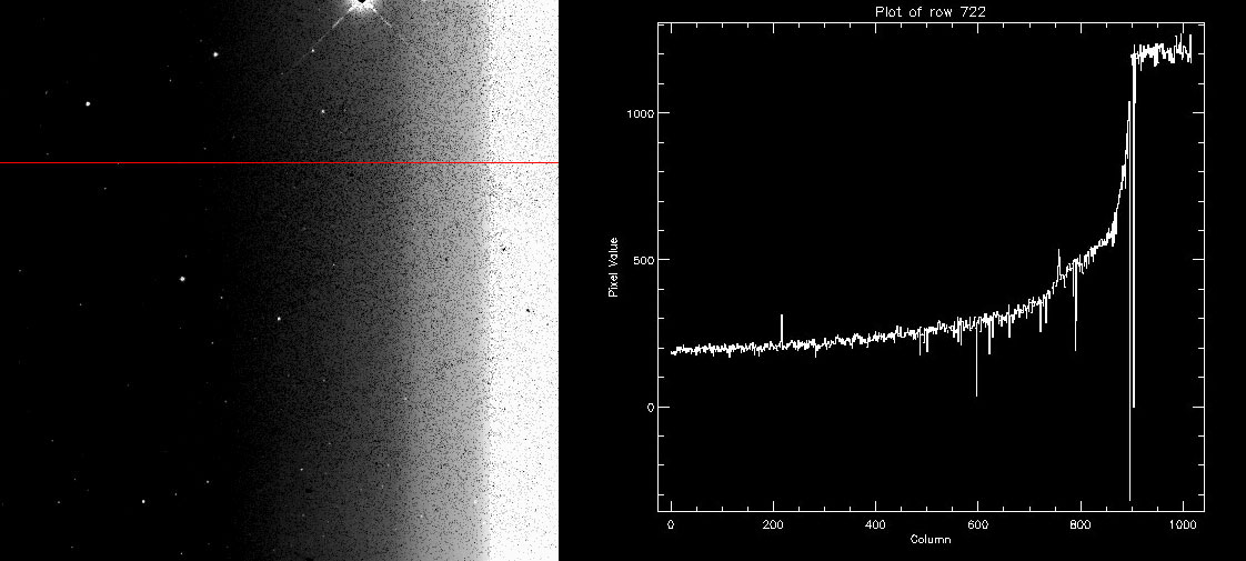 |
| Figure 61 - (Left panel) Illustration of a "TV test pattern" (scan 67842b, frame 097, Fig. 7) in W2. The red line shows the location of the row cut shown in the right-hand panel. (Right panel) Row cut illustrating the rise in counts. The signal jumped from an average of 300 DN on most of the row, to about 1200 DN at the elevated region on the right. |
Figure 62 shows the mean and maximum signal of the preceding illuminated W2 frame, and the signal jump in the TV test pattern, as a function of aperture photometry of the W2 resonant pixel halo. Figure 62 shows that there is a correlation between the signal in the resonant pixel halo and the maximum signal in the preceding frame (red symbols). This correlation is weaker for the mean signal of the preceding frameset (blue circles), and even weaker for the signal jump in the TV test pattern (green circles).
 |
| Figure 62 - The x-axis shows the aperture photometry in the W2 resonant pixel halo, and the y-axis shows, for the W2 frame immediately preceding the resonant pixel instance, the mean signal in the array (blue circles), the W2 signal jump in the TV test pattern (green circles), or the maximum signal in the array (red circles). Data for this figure are listed in Table 2. |
The resonant pixel halo is related not to a single pixel, but to a cluster of them in W2, and it is located in a region of the array where long-term latents are observed. Instances are rare and are preceded by a frameset with a dramatically elevated signal, often with a "TV test pattern" effect.
Last update: 12 November 2024