
| A Simple Background Matcher (Bmatch) | |
We summarize results from a simple background offset matching algorithm to assist in creating WISE Atlas Images (co-adds). The goal is to obtain seamless (and/or smooth) transitions between frames near their overlap regions prior to co-addition. We will want to equalize background levels from frame-to-frame, but at the same time preserve natural background variations and structures as much as possible. The bulk of variation in background levels will be due to instrumental transients, changing environments, off-axis reflections, scattered and stray light. Also, if one were to combine frames taken at six monthly intervals, i.e., if WISE were to survey the sky again, local (zodiacal) background levels will vary due to parallax effects. The plan is to perform background matching prior to outlier detection with AWOD, and obviously prior to frame co-addition with AWAIC.
Here are the main steps:
Caveat:
The above simple method will not preserve natural background gradients on scales spanning a WISE image frame (~47′), nor over the proposed ~94′ × 94′ dimensions of an Atlas Image. As a reminder, WISE has no requirements on the background. However, it may be of scientific interest to preserve structure on scales smaller than a WISE image frame. The simple method described here does just this.
Version 1 of the program (as described above) simply adds a constant median to all the frames (i.e, steps 3 and 4). A future improvement may involve computing a "median plane" over all frames in the footprint, and then adding this common plane to all frames in a manner that ensures continuity over the footprint region. This attempts to capture and retain any natural background gradient over the footprint. The important thing is that discrepancies in background levels between overlapping frames are removed before co-addition. Instrumental transients can also manifest as gradients, so one needs to be sure that any retained global gradient is purely astrophysical.
Background matching across Atas Image footprints will be accomplished within the WISE image server (interfacing with IRSA). This may not be needed if the matching is done properly (and robustly) at the intra-footprint level. If so, we then expect the median background measure from footprint-to-footprint (step 4 above) to be relatively smooth. Variations on scales of several degrees or greater (e.g., the zodiacal background) can still be reconstructed if one were bold enough to stitch together many footprints. Algorithmic details are presented in the Subsystem Design Specification document (in preparation).
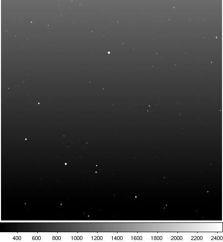
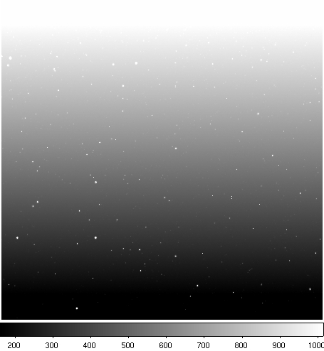
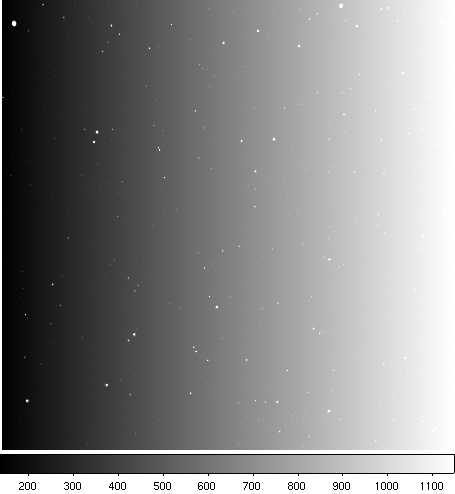
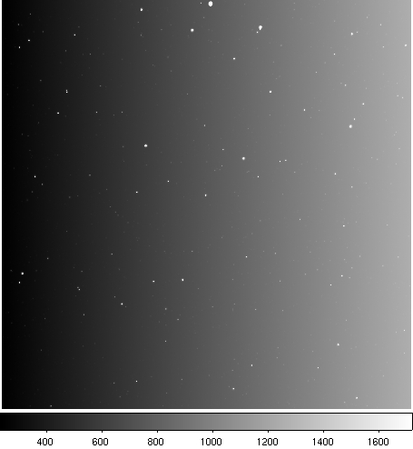
We tested our simple background matcher on a set of 12 overlapping band-1 frames from a simulation provided by Ned Wright. Details of the simulation can be found here. The raw simulated frames contained no background variations. Therefore, we added artificial backgrounds with randomly varying intensity levels and gradients. Figure 1 shows an overlapping set of frames with simulated backgrounds (all displayed with the same stretch). Figure 2 shows the same frames at the same stretch, after background matching.
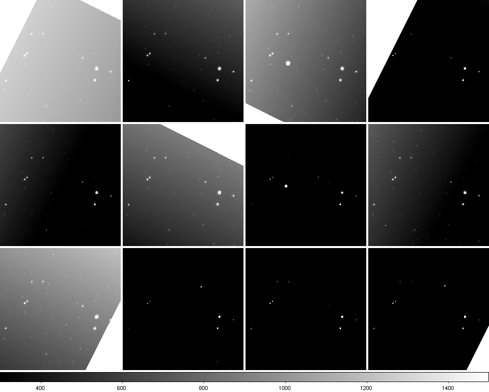 |
| Figure 1 - Simulated input frames aligned in WCS coordinates, and containing varying background levels and gradients. Each panel is a frame zoom-in spanning ~20′. Click on panel to enlarge. |
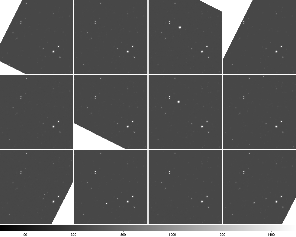 |
| Figure 2 - Same frames as Figure 1 after background matching. Uses the simple algorithm described in §2. Click on panel to enlarge. |
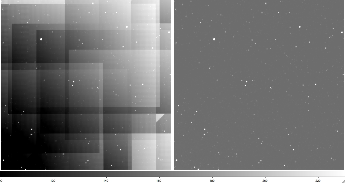 |
| Figure 3 - Left: mosaic of the above frames spanning ~45′ before any background matching. Right: same mosaic after background matching. Both mosaics were made using AWAIC. Click on panel to enlarge. |
 |
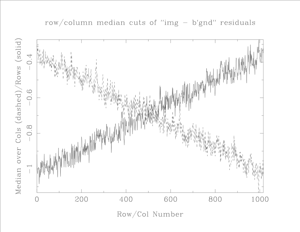 |
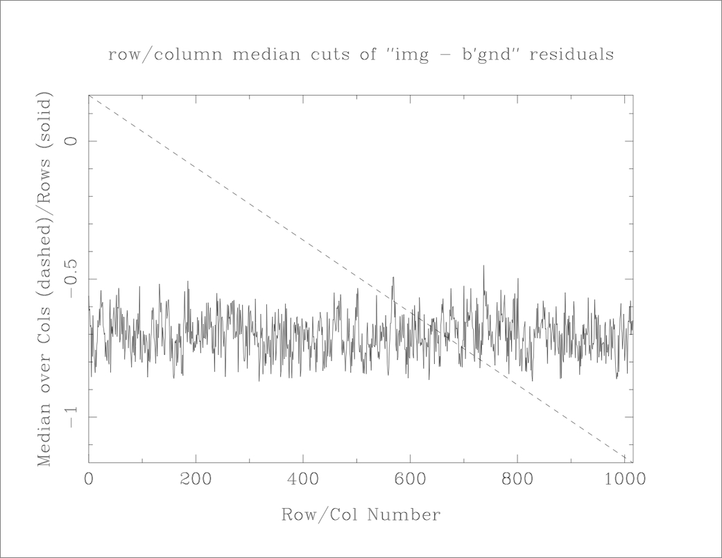
| Frame 01301d028-w1-int-1b | Frame 01301d050-w1-int-1b |
 |
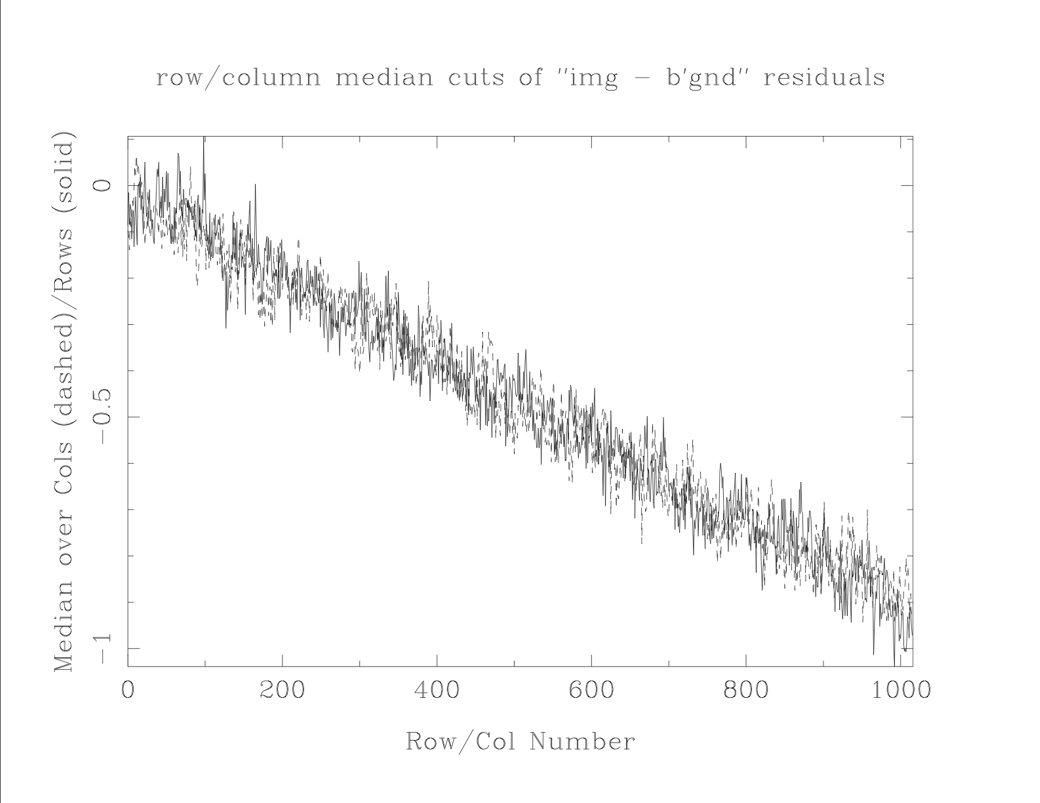 |
| Frame 01301d057-w1-int-1b | Frame 01301d061-w1-int-1b |
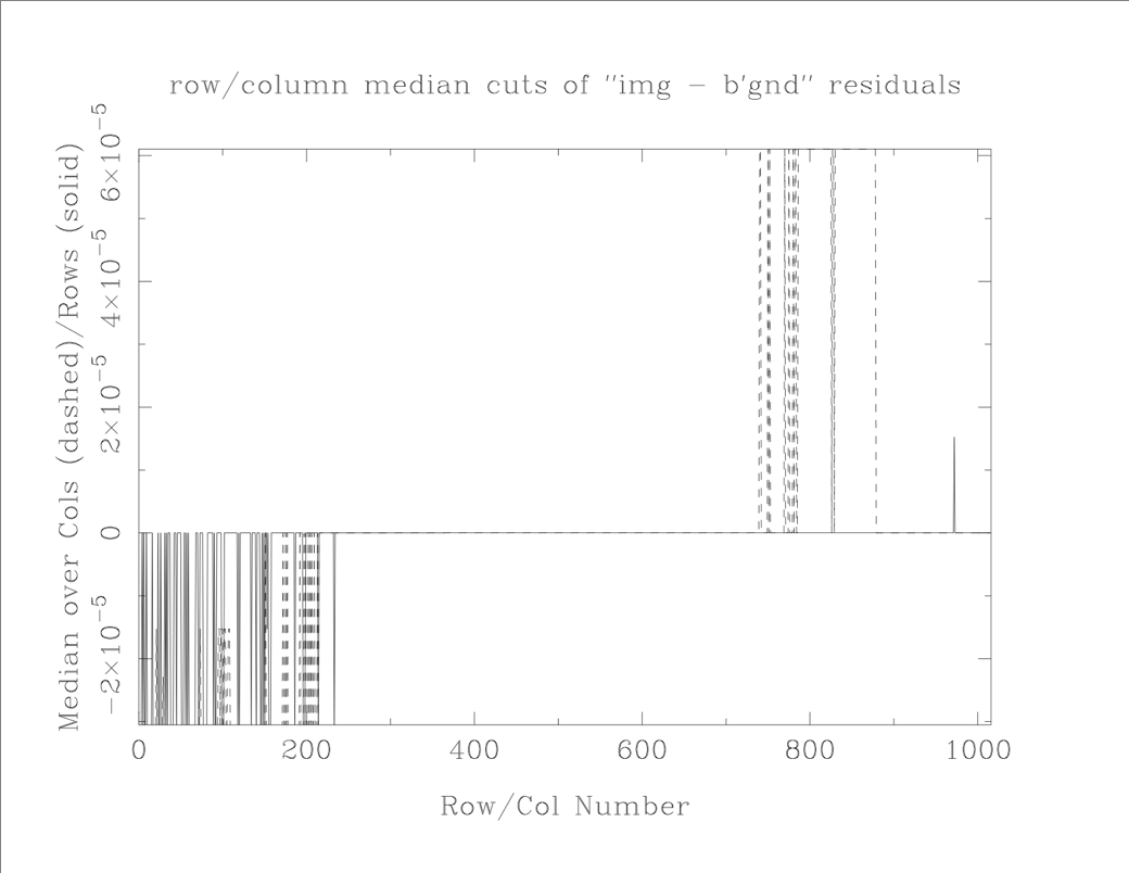
| Figure 4 - Plots of median residuals: 'input frame - background planar fit' for four of the frames above. The residuals are represented as median cuts across pixel columns (dashed), and rows (solid) versus row and column number respectively. The residuals should ideally be randomly distributed about zero, but can be affected bythe the presence of extended structure and sources, and hence the choice of regions for the planar fit. For the frames shown here, a residual of "1" on the vertical axis corresponds to an error of <0.1% in the background fit. Click on any panel to enlarge. | |