 |
| Figure 1 - MOS Architecture |


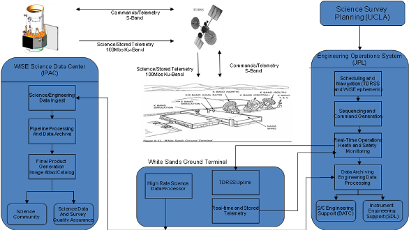
The overall WISE MOS architecture is shown in Figure 1. Spacecraft communication was via TDRSS. Engineering data was routed to the Engineering Operations System (EOS) at JPL. Science data went to the WISE Science Data Center (WSDC) at IPAC/Caltech. The Science Planning system at UCLA provided the Survey Plan. The EOS developed the sequence that the spacecraft executed. All commanding and spacecraft monitoring was performed by the EOS with the support of the spacecraft contractor (BATC) and the payload contractor (SDL).
 |
| Figure 1 - MOS Architecture |
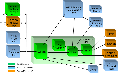
The WISE GDS architecture and data flow is shown in Figure 2. The GDS was developed and hosted by the Earth Science Mission Center (ESMC) at JPL.
 |
| Figure 2 - GDS Architecture and Data Flow |
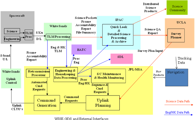
The GDS for the WISE mission was an adaptation of the GDS that was developed for the Jason Project. The WISE GDS was standalone and separate from the Jason GDS. Figure 3 depicts the core GDS in the JPL MSA and its interfaces to external elements that supported flight operations.
 |
| Figure 3 - WISE GDS and External Interfaces |
At the center of the WISE GDS was the WISE Telemetry Command and Communications System (WTCCS). It operated in a server/client relationship. The bulk of the processing was performed in the Project's dedicated high performance server. Users logged into the server with a WTCCS client program hosted on low end personal computers. The WTCCS provided the command function generating real time commands, stored sequence commands, and commands in the CFDP format. The WTCCS controlled the transmission of all ground commands including the confirmation of proper reception at the spacecraft. The WTCCS also performed telemetry processing including the generation of plots and tabulations, alarm checking, and the generation of telemetry data products for distribution and archive. The WTCCS provided support for spacecraft maintenance and health monitoring.
The WISE project installed a high rate data processor at White Sands which processed high rate telemetry (recorded science and engineering data). The science data were sent directly to the WISE Science Data Center (WSDC) at IPAC for science processing. The recorded engineering data was sent to JPL for telemetry processing, distribution and archiving by the WTCCS. The WTCCS monitored the continuity of the high rate data and generates uplink commands to replay any missing data.
During flight, the spacecraft was controlled by command sequences which are files uplinked to the spacecraft memory and executed when loaded into an onboard sequence engine. The GDS used JPL's multi-mission sequencing software (SEQGEN) which was adapted to WISE requirements to generate constraint free sequence files. Another WISE program which supported the generation of onboard sequence files is the pointing generation software (PGEN). PGEN generated all spacecraft pointing commands and verified that the resulting spacecraft attitude does not violate any pointing constraints. Spacecraft constraints which were not verified by SEQGEN or PGEN were manually verified via checklists by the Engineering Operations Team. During the course of the mission, no commands were sent to the spacecraft which resulted in constraints being violated.
The Navigation function was performed by JPL's institutional navigation personnel. Navigation used JPL software to process radar tracking data provided by the US Strategic Command (STRATCOM) to generate satellite ephemerides in several formats (IIRV and SPK). The IIRV was sent to WSC which used it to track the WISE spacecraft during a TDRSS contact. The SP kernel was used internal to the GDS to generate a spacecraft state vector that was uplinked to the spacecraft three times per week. It was also used in all applications that required spacecraft ephemeris information including science processing performed at the WSDC. The process of receiving radar data from STRATCOM and generating ephemeris products was error free with no ISA's being generated.
In this section, we describe at a high level the flow of WISE science and engineering data from downlink to archiving. WISE end-to-end data flow is illustrated in Figure 3.
Compressed, encoded science data and selected engineering telemetry was transmitted via High-Rate Ku-band transmitted from the WISE flight system to TDRS for relay to the TDRSS terminal at White Sands Complex (WSC). Some engineering telemetry is also transmitted to TDRSS terminal via Low Rate S-band relay. S-band and Ku-band downlinks occurred approximately four times per day during WISE on-orbit operations, with each contact taking approximately 15 minutes.
The WISE flight system was body-pointed to orient the high gain Ku-band antenna towards a TDRS element during each contact, interrupting survey data acquisition. Contacts were made preferentially during scans when WISE approached within 45° of the Ecliptic poles so that survey outages took place where the nominal coverage was highest.
The TDRSS terminal performed convolutional decoding of the S-band and Ku-band telemetry. Following each downlink contact, the Ku-band data were transferred to the WISE-provided and operated high rate data processor (HRP) at WSC via a 100 Mbit/sec data stream. The decoded Low Rate S-band telemetry was sent electronically to the MOS at JPL.
The WISE HRP received the science image data from the TDRSS terminal in the form of a stream of Reed-Solomon encoded AOS transfer frames. The HRP performs Reed-Solomon decoding, packet extraction and stored extracted packet files by virtual channel. The HRP generated a frame accountability report describing the overall quality and continuity of the received data. Following the processing of the data from each downlink, the HRP transfers the raw data packets to the WISE Science Data Center at IPAC electronically via 4Mbps data line from WSC to IPAC.
A copy of all science data packet files were stored on a RAID file storage system at WSC in the event that a retransmission to IPAC was necessary (none were).
The WTCCS at JPL received the S-band and Ku-band telemetry frames from the White Sands Data Complex Interface Service Capability (WDISC) and performed frame synchronization and packet extraction. The packets were channelized for processing and display and the CFDP file data were reconstructed. A subset of engineering telemetry along with assorted navigation products were forwarded to the WSDC at IPAC for merging with the raw science data. The engineering telemetry, navigation and ancillary files provided by the MOS were:
The WSDC at IPAC receives the science data packets transferred by the HRP, validated the contents of each transfer and reported the status of the validation to MOS. The WSDC received engineering telemetry files from MOS asynchronously from the science packets. Because of their smaller size, the engineering telemetry and ancillary files from MOS usually arrived at IPAC before their respective science data packets. However, this wasn't always the case if the downlink science data volume was small.
Once each electronic transfer from the HRP was complete, the WISE Science Data System (WSDS) Ingest subsystem decompressed the science data packets, and assembled them into raw FITS format images. Ancillary files were processed using NAIF library routines and custom code and along with the engineering telemetry were correlated with the science data using VTC time stamps. Relevant engineering parameters were added to the headers of the raw FITS images to create Level 0 FITS images. The Ingest system then staged the Level 0 science data for scan/frame pipeline processing.
The mean Rice compression ratios measured for the WISE raw science image data in each band are shown plotted as a function of time during the WISE mission in Figure 4. These are the average ratios of the compressed to uncompressed raw image sizes computed for each WISE downlink pass. Each pass contains on average ten scans, or approximately 2500 single-exposure framesets, so they sample a diverse range of celestial scenes. During the full 4-Band Cryogenic mission phase, the on-board Rice compression achieved average compression ratios of 0.37, 0.37, 0.48 and 0.40 in W1, W2, W3 and W4, respectively. Compression ratios increased for W1, W2 and W3 during the 3-Band Cryo phase, and for W1 and W2 during the Post-Cryo phase as detector noise increased in response to rising detector temperatures. A small-amplitude, bi-weekly increase in the W1, W2 and W4 compression ratios is seen during the 4-Band Cryo phase as WISE scanned close to the first and third quarter moon. The sharp peaks in the W3 compression ratios during the 3-Band Cryo phase correspond to times when the W3 exposure time was decreased. The broad increase in the W1 and W2 compression ratios centered near MJD=55280 is correlated with the period when the WISE scan path was close to the Galactic Plane. A similar peak is present six months later, but is less obvious, particularly in W2, because of the increasing detector temperatures during the 3-Band Cryo phase.
Scan/frame pipeline processing at the WSDC (described in Section IV), removed the instrumental signature from the raw science image frames, detected and characterized discrete sources on the images, and derived and applied astrometric and photometric calibration to the image and extracted source data. Multiframe pipeline processing combined all images covering a region of the sky and detected and characterized sources from the coadded images. Processed image, extracted source and metadata associated with both were written to the WISE science archive.
During and following data processing, the WISE Science Data Center performs quality assurance that assesses the integrity of flight system data, the completion status of data processing, and the derived characteristics of the science data relative to the WISE mission performance and data product requirements. At the completion of data processing, the WSDC in collaboration with the WISE PI and Science team generates and validates the WISE Image Atlas, Source Catalog and ancillary products for release.
WISE release data products are delivered to the NASA/IPAC Infrared Science Archive (IRSA). The WISE products are distributed to the astronomical community and general public via the on-line and computer-friendly interfaces of IRSA. IRSA also provides the long-term living archive for the final WISE science products to insure their accessibility to the community in perpetuity.
Following the end of WISE mission activities, the WSDC will send a copy of the WISE Level 0 FITS image data to the National Space Science Data Center (NSSDC) for long-term archiving.
Last update: 2016 August 8


