


The WISE flight system is 285 cm tall, 200 cm wide and 173 cm deep. It has a mass of 661 kg. It uses 301 W of power, while the solar panels can provide over 500W. The 40 cm diameter telescope sits inside a solid-hydrogen cooled cryostat. The cryostat plus telescope and camera have a mass of 347 kg, and the solid hydrogen has a mass of 15.7 kg at launch. Figure 1 shows the flight system in operational configuration.
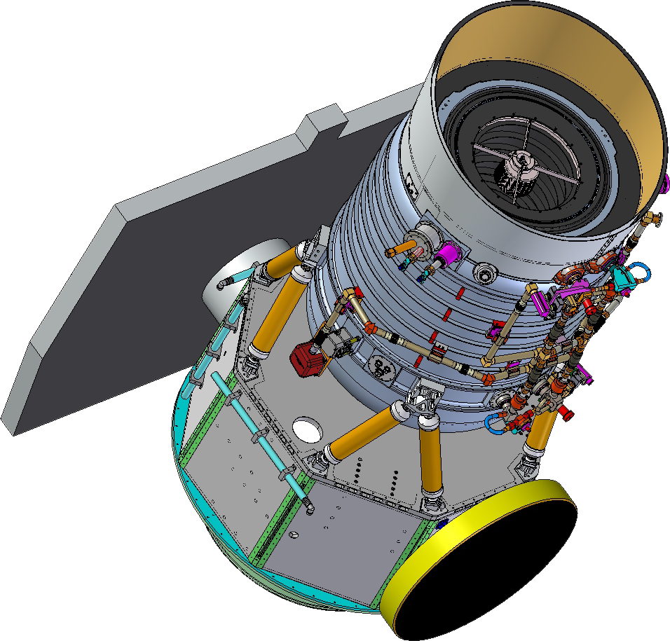 |
| Figure 1 - The WISE flight system in its operational configuration. |
The WISE instrument (Figure 2) is a cryogenically cooled infrared instrument consisting of a 40-cm aperture telescope, scan mirror, and beam splitters to separate light into four bands. Light is measured using four focal planes, two 32 K mid-wave infrared (MWIR) HgCdTe focal plane arrays (FPA) and two 7.8 K long-wave infrared (LWIR) Si:As FPAs. The entire optical assembly is housed within the two-stage solid-hydrogen cryostat. The sole purpose of the primary tank is to cool the two LWIR FPAs, while the larger secondary tank cools the rest of the optics to less than 17 K. The optical assembly mounts to a single interface flange within the cryostat for simple and reliable integration and ease of removal during the testing sequence. The primary tank is connected to the LWIR FPMAs via a flexible, shrink-fit style, thermal link. The link consists of beryllium end fittings attached to copper braids. A deployable aperture cover hermetically seals the vacuum shell during ground operations and is jettisoned on-orbit to open the telescope aperture to view space. The WISE instrument is thermally isolated from the spacecraft, allowing the outer shell to be passively cooled to below 200 K on orbit to limit parasitic heat loads into the solid hydrogen.
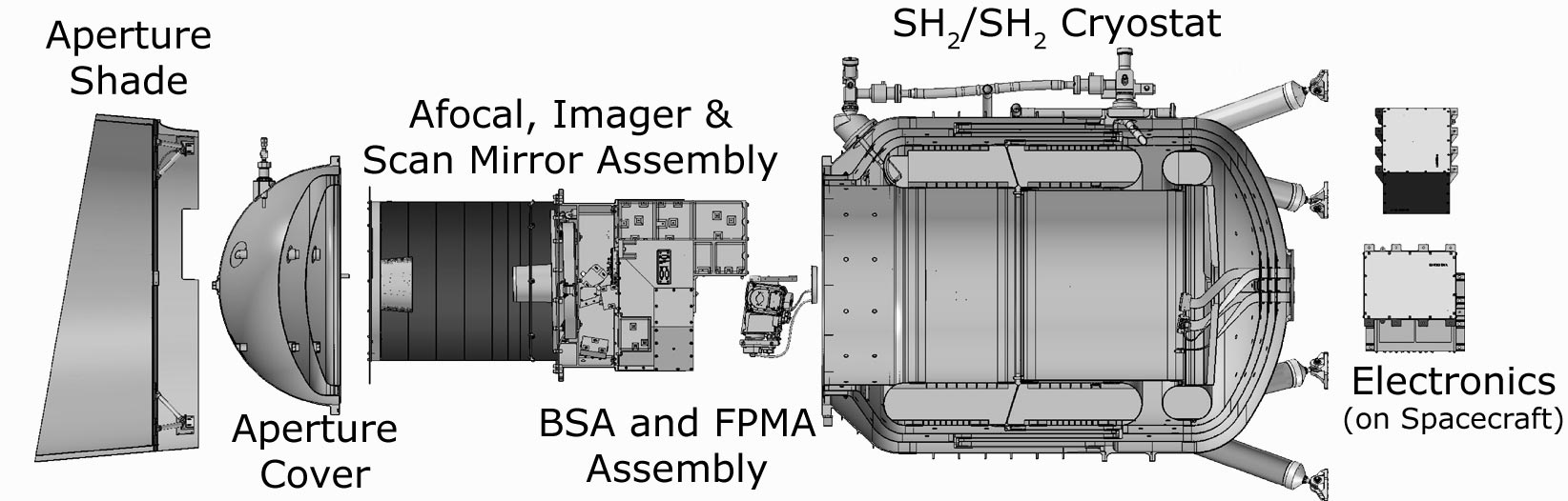 |
| Figure 2 - WISE Instrument Configuration |
WISE has adopted the 2MASS strategy of moving the telescope at a constant inertial rate, and using a scan mirror to freeze the sky on the arrays for the integration time. The field of view (FOV) of WISE is 47', and by choosing to have a small (10%) overlap between frames, the cadence between frames is set at 11.002 seconds per frame. For WISE 8.8 seconds of this is spent integrating and it takes about 1.06 seconds to read out the arrays. The LOS then jumps forward 42' in 1.1 seconds. There are about 15 orbits per day, so the scan circle advances by about 4' per orbit, giving about 12 orbits where the FOV hits a given source.
The WISE telescope, imager, dichroic beam splitter, detectors, and cryostat were built by the Space Dynamics Laboratory of Utah State University with major subcontracts from Lockheed Martin Advanced Technology Center, L3 Communications SSG-Tinsley, and DRS Technologies. Larsen & Schick (2005, Proc. SPIE, Int. Soc. Opt. Eng. Vol. 5904-166) describe the WISE science payload in more detail. The instrument was tested, then passed a vibration test, and was tested again, before being delivered to Ball Aerospace in May 2009 for final integration with the spacecraft. The testing included a determination of the optimal focus, a measurement of the point spread function, and a determination of both the relative spectral response and the absolute sensitivity of the system.
The WISE short-wavelength channels employ 4.2 and 5.4 μm cutoff HgCdTe arrays fabricated by Teledyne Imaging Sensors with 1024 x 1024 pixels each 18 μm square. For the long-wavelength channels, the detectors are Si:As BIB arrays from DRS Sensors & Targeting Systems with the same 1024 x 1024 pixel format and pitch. The first four and last four pixels in each row and column are used as non-illuminated reference pixels, so the effective size of the arrays is 1016 x 1016 pixels. The median pixel scale is 2.757"/pixel with a range of ±0.6% among the different axes and arrays. The band 4 data is binned 2 x 2 on board, giving 5.5"/pixel. All four arrays image the same field of view simultaneously using three dichroic beam splitters.
All of the arrays use sampling up the ramp. The 11 sec cadence between frames is divided into 10 parts. A reset-read of the arrays occurs during the first 1.1 sec, followed by 8 read cycles each 1.1 sec apart and a final reset cycle while the scan mirror flays back. For the W3 and W4 arrays the 9 reads are multiplied by weights of -4, -3, -2, -1, 0, 1, 2, 3 & 4 and summed to give the slope of the ramp. The W1 and W2 arrays showed excess noise in the first sample so the weights used are 0, -7, -5, -3, -1, 1, 3, 5 & 7.
The HgCdTe arrays are sensitive from ultraviolet wavelengths out to ~5.4 µm; the Si:As arrays are sensitive to wavelengths as long as 28µm. All four WISE arrays have been anti-reflection coated to maximize their in-band responses. The nominal operating temperature for the HgCdTe arrays on WISE is 32 K; their temperature is maintained by using active heaters. The Si:As arrays operate at 7.8 K. This temperature is passively set by making a good thermal connection between the Si:As arrays and the primary tank of the WISE hydrogen cryostat. Table 1 summarizes the measured WISE detector performance for all four bands.
The Si:As FPAs were equipped with heaters so that they could be
thermally annealed on orbit twice per day to purge accumulated long-term
latent images. During an anneal cycle, the Si:As FPAs were heated
for two minutes to approximately 15K from their nominal 7.8K operating
temperatures.
W3 and W4 data were unusable for approximately 2000 seconds
following the anneals because of elevated and rapidly changing detector dark
current, read noise and responsivity. One anneal per day was performed
during a TDRSS contact but one was conducted during normal survey scanning,
resulting in W3 and W4 coverage loss.
| Parameter | HgCdTe Performance (W1 and W2) | Si:As Performance (W3 and W4) |
| Wavelength Range (µm) | 2.8-3.8 (W1) 4.1-5.2 (W2) |
7.5-16.5 (W3) 20-28 (W4) |
| Operating Temperature (K) | 32±10.1 | 7.8±0.5 |
| Array Format | 1024x1024 | 1024x1024 |
| Quantum Efficiency (mean over band, with AR coating (%) | >70 | >60 |
| Pixel Pitch (µm) | 18 | 18 |
| Pixel Operability | >90% | >90% |
| Dark Current (mean, @ operating temperature) (e-/sec) | <1 | <100 |
| Read Noise (e-, CDS rms) | 19 | 103 |
| Well Capacity (e-) | >100,000 | >100,000 |
| Power Dissipation (mW) | 6.7 | 3.7 |
| Outputs | 16 | 4 |
The optical design and assembly of the WISE telescope and camera was done by L-3 Communications SSG-Tinsley. The optics consist of an afocal 40 cm diameter telescope that produces a parallel beam of light that is fed into the scan mirror, which works in the parallel beam, and then into the all-reflecting camera. There are six mirrors including folding flats in the afocal telescope before the scan mirror, and six mirrors in the camera after the scan mirror. All of the mirrors are gold-coated giving a high infrared transmission. The design is described in more detail by Schwalm et al. (2005, Proc. SPIE, Int. Soc. Opt. Eng. 5904-20). The telescope is a 13-mirror, all-aluminum system that uses gold-coated, bare-polished aluminum mirrors. The cryogenic scan mirror is placed in collimated space between the afocal telescope and the imaging optics. The optics operate at less than 17 K to keep the instrument background low.
The optical design, shown in Figure 3, is comprised of two subsystems separated in collimated space by an internal scan mirror. The first is an 8X magnification, 40 cm aperture afocal telescope with a field of view of 47 x 86 arcmin. The second is an F/3.38 imager with a field of view of 6.3 x 6.3 degrees, corresponding to 47 x 47 arcmin in object space. The scan mirror is positioned at the exit pupil of the afocal telescope and the entrance pupil of the imaging module.
A beamsplitter assembly (BSA) separates the incoming light into four separate channels which are simultaneously imaged. The BSA is an aluminum structure that holds three beam splitters that separate the light from the imager into the four bands. The BSA provides the physical interface between the imager and the focal planes. Composite thermal isolators are used between the FPMA mounts for bands 3 and 4 and the BSA, providing the thermal isolation needed to achieve the lower temperatures for the two Si:As FPAs, which are thermally strapped to the primary tank. Heaters are provided so that these FPAs can be annealed on orbit.
The imager module feeds four channels centered on 3.4, 4.6, 12, and 22 µm, each with a 1024 x 1024 pixel array focal plane. The 47 x 47 arcmin fields of view of each array overlap in object space. As the spacecraft pitches at 3.8 arcmin/sec to match the WISE orbital rate, the scanner backscans at the equivalent rate for the duration of the 9.9 second integration (8.8 seconds for any individual pixel; 9.9 seconds for the entire array) in order to freeze the LOS on the sky. As a result, the focal planes' FOV sweeps from one end of the afocal field of regard to the other during the integration.
The afocal telescope design includes five powered mirrors and a fold mirror: a Cassegrain-like objective with a fold feeding a reflective triplet. The design was strongly driven by the extremely low distortion required to perform internal scanning during focal plane integration without blurring the image: distortion of less than two-tenths of one percent is required across the full 47 x 86 arcmin afocal field.
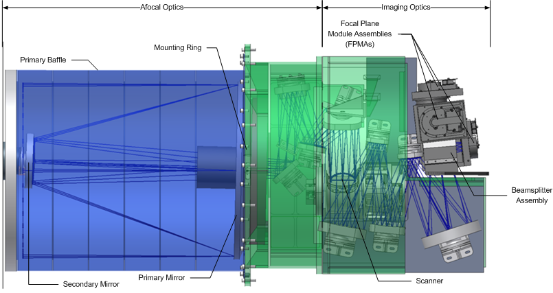 |
| Figure 3 - The WISE optical assembly includes an afocal telescope, imager module, and scan mirror assembly, and supports the beamsplitter assembly that includes the focal plane arrays. |
A fold mirror is included between the scan mirror and imager to package the optical train within the cylinder diameter defined by the primary mirror and to locate all the focal planes at the end of the cryostat. The four spectral channels are separated by three beamsplitters in the final f-cone, with the first beamsplitter reflecting the 3.4 and 4.6 µm channels and passing the 12 and 22 µm channels, and then a beamsplitter in each divided path reflecting the shorter channel (3.4 and 12 µm) and transmitting the longer channel (4.6 and 22 µm, respectively).
The structure is a modular design. An afocal telescope module mounts to the cryostat interface flange and supports the five-mirror afocal telescope, including a metering tube with baffle vanes and the secondary mirror spider. An imaging module attaches to the back of the afocal module and houses the five-mirror imaging optics. This imaging module also supports the scanner and the beamsplitter assembly module.
A one-axis scan mirror assembly is located in collimated space at the exit pupil of the afocal telescope, which corresponds to the entrance pupil of the imaging module. The scan mirror scans the square field of view of the detectors, as presented by the imaging module, across the rectangular field of regard of the afocal telescope. The operating profile is a 9.9 second scan and a 1.1 second flyback, with a scan angle of 2.5 degrees (at the scanner shaft; this range corresponds to a 0.625 degree LOS scan in object space due to the afocal telescope magnification). Figure 4 and Table 2 show the scanner and its parameters.
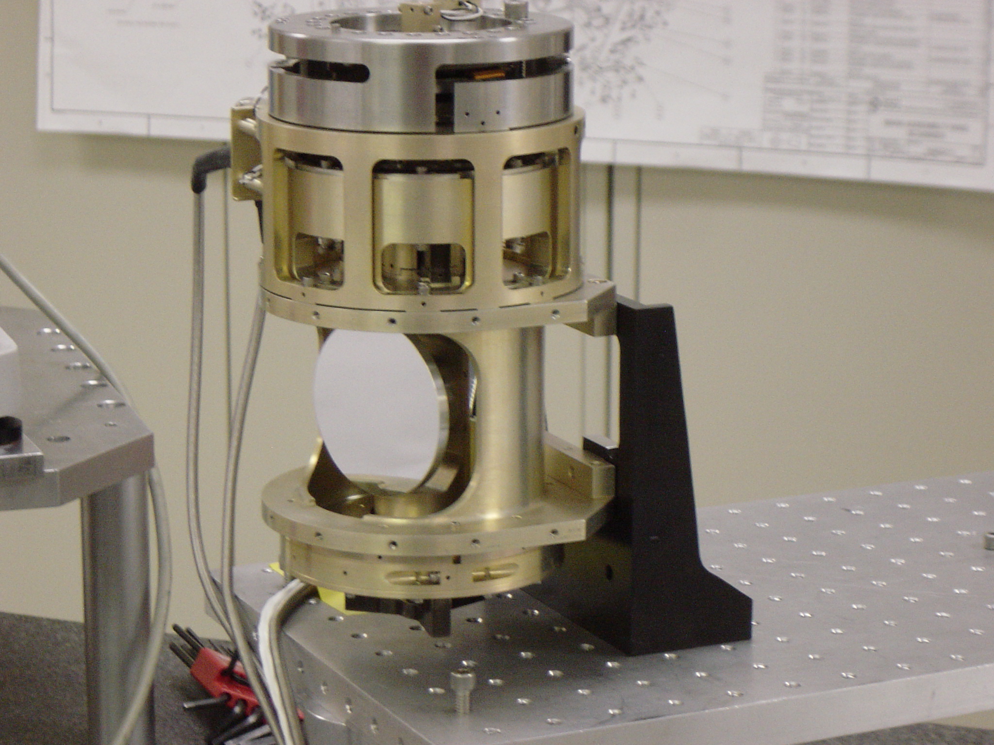 |
| Figure 4 - The WISE scanner |
| Operating Temperature | 4-17 Kelvin |
|---|---|
| Design Life | 3.5 million cycles |
| Scan Linearity Requirement | < 5 Arcsec |
| Jitter Requirement | < 1.5 Arcsec |
| Scan (Shaft Angle) | 1.7-2.6 degrees |
| Scan Duration | 9.9 seconds |
| Fly-back Duration | 1.1 seconds |
| Power Dissipation in Cryostat | < 4 mW Max |
The cryostat (Naes, Wu, Cannon, Lloyd and Schick 2005, Proc. SPIE, Int. Soc. Opt. Eng.
5904-41) was built by the Lockheed Martin Advanced Technology Center (Figure 4). It uses solid hydrogen to cool the telescope to less than 12 K, and the Si:As arrays to less than 7.5 K. There are two tanks of solid hydrogen: a larger secondary tank that cools the telescope and optics, the short wavelength arrays, and shields around the smaller primary tank that just cools the Si:As long wavelength arrays. Schick & Lloyd (2009, "Astronomical and Space Optical Systems," Proceedings of the SPIE, Volume 7439, pp. 743917-743917-7) describe the cryostat support system and test results. The 186-liter secondary tank is used to cool the majority of the optics to below 17 K and to intercept the bulk of the parasitic heat loads, thus reducing the heat loads on the primary tank to insignificant levels. The 24.4-liter primary tank is used solely to cool the Si:As focal planes modules to 7.8±0.5 K. Both tanks are filled with 1.7% dense, 1100 aluminum foam to provide heat exchange from the hydrogen to the tank walls. The design allows for both ground and on-orbit operations. The cryostat was required to provide cooling to support a seven-month mission; the actual performance exceeded this requirement and provided a total of 7 months and 3 weeks.
A two-stage aperture shade minimizes the thermal backload into the telescope and protects the telescope from the external environment. The outer stage or shade attaches directly to the cryostat vacuum shell. The inner shade is isolated from the outer shade and is radiatively cooled to less than 110 K. A pyrotechnically actuated aperture cover hermetically seals the vacuum shell during ground operations and is jettisoned on-orbit to expose the telescope aperture. The WISE instrument is thermally isolated from the spacecraft. The thermal isolation allows the outer shell to be passively cooled to < 200 K on orbit to limit parasitic heat loads into the solid hydrogen. Four fiberglass bipod strut assemblies support the instrument off the spacecraft, providing the necessary launch support for the instrument and necessary thermal isolation.
 |
| Figure 5 - WISE Cryogenic Support System Features |
The 26.8-liter primary tank is used exclusively to cool the two LWIR FPMAs, thus minimizing the risk in achieving and maintaining the LWIR interface temperature of 7.6 K. The 197-liter secondary tank cools the telescope to an interface temperature of < 13 K. It also guards the primary tank, reducing parasitic heat loads into the primary to insignificant levels. Both tanks are filled with a 1.7% dense 1100 aluminum foam heat exchanger to limit tank end-of-life (EOL) temperature drops and to make the tanks isothermal. The tank sizing is based on a 78% solid fill fraction to allow the cryogen to completely melt during ground hold without venting.
Last update - 2012 March 6