IV. WISE Data Processing
2. Data Ingest
Contents
a. Data Transfer
i. Data Storage
ii. Manifest Files
iii. Output Log
iv. The Working Directory
b. MOS Ingest
i. MOS Data Requirements
ii. MOS Data Delivery Cadence
iii.Ancillary Data Database Generation
iv. MOS Ingest Metadata Table Output
c. HRP Ingest
i. Image Reconstruction
ii. Correlation to Ancillary Data
iii. Level 0 Image Creation and Archive Update
iv. Scan ID and Frame Number Assignment
v. Frame Index Update
vi. Recovery From Telemetry Errors
vii. Frame Accounting
viii. Scan Pipeline Kickoff
ix. HRP Ingest Meta-data File Output
d. Quicklook Processing
2. Data Ingest
The Ingest subsystem at the WSDC was responsible for assembling
Level 0 images from various mission ancillary
data products from the Mission Operations System (MOS)
and science image data from the High Rate
Processor (HRP).
Deliveries include the following:
- Transfer manifest files: list of transfer contents
- HRP image data as raw source packet telemetry
- Mission ancillary data
- SCLK, LSK files: time adjustment and conversion
- PEF files: predicted spacecraft events
- CK files: spacecraft orientation
- Planet SPK files: planetary body position
- S/C SPK files: spacecraft position
- H/K CSV files: housekeeping telemetry
- Ground track files: spacecraft geographic longitude, latitude and altitude, and
great circle distance distance from SAA boundary
Ingest has six primary functions:
- Detect data transferred to the WSDC ingest and move those data to archive locations ready for further
processing
- Interpret mission ancillary data sent by MOS and construct internal
databases for use in data processing
- Depacketize and decompress image data from the HRP and correlate it with
mission ancillary data to create Level 0 images (L0)
- Initiate downstream Quicklook and Scan/frame pipeline processing
- Write/update L0 meta-data to the Frame Index (FIX)
- Provide QA metrics on the L0 images, mission ancillary data, and the ingest
process

|
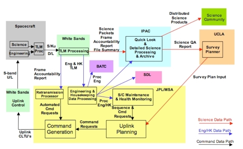
| Figure 1 - End-to-End Data Flow |
Ingest carries out its primary functions in three distinct stages:
- Data transfers archived and copied, triggering
subsequent steps IV.2.a.
- Mission ancillary data ingest upon delivery by MOS
IV.2.b.
- HRP ingest upon delivery; this stage also does pipeline kickoff
and FIX updating IV.2.c.
a. Data Transfer
The transfer process verified data for completeness and integrity
and stored the transferred files on
the WSDC operations system at IPAC. Copies of these data were used for the actual
ingest process allowing the original data to remain untouched.
i. Data Storage
Data integrity checking ensured that each file
transfer was complete and uncorrupted. Files were
compared against their accompanying manifest to verify that file names
and sizes were as expected.
ii. Manifest Files
A summary of a transfer's contents was created and saved for
later reference.
iii. Output Log
A log file containing a record of all actions taken was then
created, saved and subsequently reviewed by the operations staff.
iv. The Working Directory
Each time the completion of a new delivery was detected, all
data were copied into the operations working directory and
validated. All subsequent ingest occurred out of the working directory.
b. MOS Ingest
The MOS at JPL is responsible for delivering all ancillary data,
i.e. non-image meta-data
necessary for subsequent data processing and evaluation.
 |
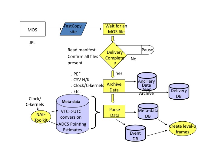
| Figure 2 - MOS Data Ingest Overview |
i. MOS Data Requirements
Every ingest of HRP data (WISE science images) requires that the following MOS
ancillary data be up to date, i.e. the most recent data available must have
already been transferred and ingested:
- LSK, SCLK files
- PEF files
- Ground track files
- Planet SPK files
- CK files
- H/K files
If any of these files are missing or out of date, HRP ingest
was aborted, then restarted when all prerequisites were present.
ii. MOS Data Delivery Cadence
SCLK clock kernels were updated roughly weekly and on an as-needed basis. PEF and ground track
files were delivered twice a week, associated with the command sequence generation cycle. All
other MOS ancillary data were derived directly from telemetry downlinks and were transferred
ahead of the associated HRP image data.
- LSK files:1 used over the life of the mission
- SCLK files: about once per week
- PEF, Mission plan, ground track and other SEQGEN/WOE files: twice a week
- CK, SPK files, H/K telemetry files: delivered after each downlink, approximately four
times a day, arriving prior to HRP data
iii. Ancillary Data Database Generation
All MOS deliveries were handled by a common ingest pipeline with
the actions to be taken driven entirely by what files were present
in the delivery. The many MOS data file types were then segregated
by the file name suffix, and
each type was handled in its own specialized manner.
1. LSK, SCLK DB
The Leap Second Kernel (LSK) is a
SPICE kernel, describing the
translation between ET and UTC. The Spacecraft Clock Kernel
(SCLK) is also a SPICE kernel
describing, with the LSK, the translation between Vehicle Time Codes (VTC) and UTC dates
and times.
The clock kernel files are cumulative, that is, they include data that cover the whole
mission up to the final time covered by the file. Thus, each
new SCLK kernel ingested simply replaced previous
versions.
2. CK DB
The C-kernel (CK)
files are SPICE C-kernels describing spacecraft
orientation. C-kernels (like SP kernels below) form a complete
database when all CK files are read in time order by NAIF
library routines.
3. SPK DB
The SP-kernels (SPK)
files are SPICE kernels describing the ephemerides of various
orbiting bodies, particularly the moon, planets and, most especially the WISE
satellite. SP-kernels (like C kernels above) form a complete
database for the mission when all SPK files are read in time
order by the NAIF library routines.
NAIF library routines are directed by the ingest pipeline to
read all C- and SP-kernels within a selectable time window
which covers the time period of the data being ingested and
they, in concert with the LSK and CLK kernels, then provide
all needed functionality for determination of spacecraft
position and estimated orientation vs. time.
4. Ground Track DB
The ground
track file contains ASCII record-oriented, time-stamped
spacecraft longitude, latitude, altitude and SAA distance
information.
5. Predicted Event File
The Predicted
Event File (PEF) is a Sequence and Command Generation (SEQGEN)
product which records start and stop times for a set of
interesting on-orbit events. Events of greatest interest to
ingest and pipeline processing are extracted and reformatted
into an event table. The orbit number (which is used to generate
the scan ID of the scan in which the event occurred) is also
recorded.
6. Mission Plan DB
Mission
Plan files, which originate at the SOC (UCLA), are test files
passed to the WSDC via MOS. These files were archived for future
reference.
7. H/K DB
The housekeeping (H/K) telemetry data were delivered to the WSDC as a
series of compressed CSV files, correlating
time to the various telemetry values. These
files were combined to
produce a cumulative, SQL-searchable DBMS of H/K data indexed on time.
iv. MOS Ingest Metadata Table Output
Various summary statistics and other data were written to a metadata table
for each MOS ancillary data delivery.
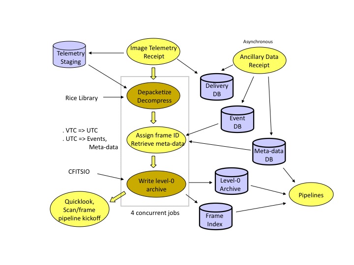
c. HRP Ingest
The High Rate
Processor (HRP) at the White Sands Complex
received telemetry from the TDRSS ground
station, stripped off communication packet wrappers and organized
the underlying source packets into four time-ordered output files,
one each for all images in a given WISE band included in that
transfer. These, along with a manifest file, comprised an HRP
delivery to the WSDC. In each band's file for a given delivery, images are
stored as a stream of compressed images tagged with the image's VTC
in the CCSDS secondary packet header. The ingest process stripped
off the source packet metadata and assembled and decompressed
for each band into FITS format and
rotated the images to a common
orientation. Ingest then associated (correlated) the image data via
the VTC (converted to UTC using the SPICE LSK and CLK kernels) with
various mission ancillary data, which were written, along with
standard FITS image definition data, to the
FITS header. This comprised the L0 data product and was saved in
the permanent Level-0 Archive.
Each delivery included
data from an average of about 8 scans. A Quicklook
Pipeline was
run for a selected subset of the images for
each delivery for rapid survey quality evaluation. All completed scans
in a delivery were submitted for full processing by the Scan/Frame
Pipeline.
 |
| Figure 3 - HRP Data Ingest Overview |
i. Image Reconstruction
Telemetry files sent from the HRP are time-ordered CCSDS source packets for
one band covering the time range for that delivery. The packets were read as
streams and the
CCSDS packet headers were used to establish the start and end
positions of images in the stream, the VTC, and how much data was in the terminal packet (the
only one which might have fill data). The data portion of each source packet (i.e.
with packet headers and fill data stripped off) for a given image are appended to one another
to produce the completed image. The image
data was passed to the Rice decompression library to produce a decompressed image.
Packet header data, mainly the VTC, was saved for each image for later use.
Every packet header was examined for internal consistency by checking the following:
- Do sequence numbers start at 0 and increase sequentially?
- Are all the VTCs for a given image the same?
- Are packets the expected size?
- Are all packets full (no fill data) except the final packet?
- Are other CCSDS packet header fields as expected (version, type, apid)?
- Did the image data decompress to an image of the correct size?
If any of these checks failed, the packet was assumed to be
corrupted, an error generated, the image was skipped
and ingest processing continued.
If all checks were successful, the raw image was
ready for correlation with the ancillary data.
ii. Correlation to Ancillary Data
To be processed by the Scan/Frame Pipeline, image data must be
associated with mission ancillary data. All
ancillary data was either present, or processing could not
continue.
The ancillary data required is listed below in rough order of importance:
- SCLK and LSK files covering the data's time range to convert VTC to UTC
- PEF file to record event table entries for:
- the orbit number, and thus the scan ID
- start/stop times of science scans
- entry/exit times to/from the SAA boundary
- anneal times
- moon avoidance zone impingements
- Earth occultations
- CK file to convert the VTC to a boresite orientation
- An SPK file recording the WISE ephemerides to establish
spacecraft position and velocity vectors.
- H/K files to record instrument temperatures, ADCS state,
instrument parameter values, momentum dumping status, etc.
- Planetary SPK file to establish moon and planet
positions
- Ground track to establish distance from the SAA boundary
Other SEQGEN files, such as the mission plan file, were also delivered, but these
were not used in Level 0 image construction.
All data listed above were queried by image VTC to get the requested
data. These data were then saved as metadata associated with the
image and in the Level 0 image FITS header.
iii. Level 0 Image Creation and Archive Update
With the raw image and correlated ancillary data in hand for each image, the Level 0 FITS image
is created as follows:
- Image pixels were converted from two-byte integers to four-byte IEEE floats.
- All bands were flipped/rotated to align with band 1.
- The FITS header was updated with the following data:
- Standard FITS image definition information
- UTC of the exposure.
- FITS WCS values representing
the rough initial image center and rotation.
- Orbit events.
- Distance and direction to the brightest solar system objects.
- The satellite's orbit position and velocity vectors.
- The spacecraft's geographic latitude,
longitude, altitude and SAA boundary distance.
- Image pixel statistics.
- Housekeeping telemetry data
- The Level 0 FITS image was saved to a file name
determined from the scan ID and frame number (see below).
iv. Scan ID and Frame Number Assignment
The event table provides start and stop times for science scans, and with them a unique
scan ID for that scan. The scan ID was derived as follows:
- The orbit number is given for each NEP and SEP crossing
listed in the event table.
These numbers were assigned by the SEQGEN software at MOS. NEP crossings result in
integer orbit numbers, SEP crossings result in half-integer numbers.
- When a science scan event was encountered, it was assigned a scan number of twice the
orbit number, a.k.a. the half-orbit number. The half-orbit number is zero-filled on the
left to five digits.
- To complete the scan ID, a letter was assigned based on the sequence of scans
started in the half-orbit so far. The first scan begun in a half-orbit
gets 'a,' the next 'b,' etc. Images in a given half-orbit not in a science scan
were assigned 'x.'
For example, suppose the PEF lists the orbit number as 1506.5 after a particular SEP
crossing. The half-orbit number is 3013. The second scan that starts in this would
produce the scan ID 03013b.
"Frame numbers" (a frame is an image and associated
meta-data)
were assigned to each image based on the
time elapsed from start of the scan (as recorded
in the event table) to the start of the image's exposure in
integer counts of 10 second bins as follows:
n(frame) = int((t(frame) - t0(scan)) / 10) + 1
where t(frame) is the image time,
t0(scan) is the the scan start time, and n(frame) is the resulting
frame number.
Note that using bins of 10s leads to non-sequential frame
numbers. This was necessary to guarantee unique frame numbers
even when the spacecraft clock was being adjusted during a scan.
v. Frame Index Update
Some of the metadata associated with each Level 0 frame were written to the Frame Index,
a set of RDBMS tables that tracked important image information
and the progress of every frame as it
was processed. The key data in the Frame Index are:
- Scan ID and frame Number
- Frame time in UTC
- The ingest success/failure status
- The ADCS estimated RA, Dec, Twist of the image center
- A spatial bin
- The time of the most recent anneal
- The directory where Scan/Frame pipeline processing would occur
The image center position, spatial bin, and frame time columns were indexed.
Subsequent processing, such as by the Scan/Frame Pipeline, updated other columns in
the Frame Index to track processing progress and record QA data.
vi. Recovery From Telemetry Errors
Ingest of the image telemetry packet stream occasionally generated errors due to packets
being corrupted or lost in transmission. When this happened,
the corrupted image was discarded and processing continued
after resyncing to the start of the next image in the
stream. All complete images not affected by corruption were
ultimately extracted from a telemetry file.
vii. Frame Accounting
Frame accounting was done on an ongoing basis to ensure there
were no major communication problems. This accounting was
entirely advisory as it was not possible for the WSDC to
initiate any actions to retrieve missing data.
When frame images were lost in communication from the satellite to the
WSDC, they were often, but not always,
retransmitted by an automated accounting process at MOS.
Thus images for a given scan may occur not only separated into
multiple deliveries but out of order. In any given ingest run
it was therefore impossible to
know what missing frame data in a scan might ultimately
appear. Thus frame accounting could only be done well after ingest
completed, when no more frames for a scan could be downlinked.
Counting missing frame data was done in a few different ways:
- Checking that frame data roughly fill the available time in a science scan.
- Checking that the centers of all images in a scan
are within about 0.7 degree of prior and subsequent images.
- Checking that neighboring images were exposed no further apart than about 11s.
viii. Scan Pipeline Kickoff
The Scan Pipeline was started for every scan which had all expected frames, or for which a
drop-dead time interval since the last frame to be received had
passed. The Scan Pipeline would in turn start an instance of the
Frame Pipeline for every frame with Level 0 image data.
Ingest created the output directories for frames known to be present in the
scan and the Frame Pipeline created symlinks to the Level 0
images for that frame and copied ingest meta-data. These, the
Frame Index, and static calibration data form the
prerequisites for Scan/Frame processing.
ix. HRP Ingest Meta-data File Output
Meta-data files recording detailed information for all frames received was
saved with the Level 0 archive and in the Scan/Frame
Pipeline processing directories.
d. Quicklook Processing
For each delivery, the ingest process started one
Quicklook pipeline to run on approximately
100 frames per delivery to get
an immediate, preliminary look at data quality. Frames were selected based on
the sky location exposed, statistical properties, calibrators in-field, and
observation time,a s well as a population of random frames.
The selection criteria were meant to emphasize frames that will give clean PSF
measurements to confirm that the scan mirror is in sync with
our scan rate.
The Quicklook Pipeline is the Scan Pipeline with command line parameters set such that:
- no dynamic calibration will be done
- higher-than-usual SNR thresholds are applied to source detection
- specialized QA is done
A composite PSF was generated by Quicklook combining data from
all the frames selected, and its properties were evaluated to
confirm scan synchronization.
Last update: 2011 May 18
Previous page Next page
Return to Explanatory Supplement TOC
Return to Explanatory Supplement TOC


