 |
| Figure 1 - Examples of diffraction spikes for stars of various brightnesses. White regions indicate saturated or bad pixels. The field of view is about 25 arcmin on a side. |
ARTID is the artifact identification module for the WISE pipeline. It is constructed under the assumption that image flaws and features in the WISE data are geometrically associated with bright sources. Bright stars produce various artifacts in the single frame images. Among these are diffraction spikes, scattered-light halos, optical ghosts, and latents. Diffraction spikes and halos, optical ghosts, and latent images have all been characterized using simple functions and geometric models which relate their positions relative to a parent bright object. Extracted sources which fulfill these criteria are marked in the "cc_flags" column of the database with the characters "d" (diffraction spike, "h" (diffraction halo), "o" (optical ghost), "p" (persistence or latent image), or "0" (no artifact). Capital characters indicate that the artifact may be producing a false spurious source; lower case letters are used for real sources which may be contaminated by excess flux from the artifact. Descriptions of the artifacts, flagging procedures, and parameter determination are given in the following sections. A full list of parameters used by the ARTID code may be found at Preliminary Release ARTID Parameters. Note that single-frame artifact flagging is treated differently from artifact flagging in atlas tiles. Most prominently, in the single frame pipeline only sources within the frame in question are considered as potential parent sources for diffraction spikes and optical ghost artifacts. In the multiframe pipeline, all sources within the Atlas image are considered as potential diff spike, halo, and ghost parents. Off-frame/off-coadd artifact parents will be included in the final WISE release pipeline. Other ways in which the WISE single band artifact identification differs from multiband ARTID include the combined treatment of diffraction spikes and halos, the lack of WISE band 1 (W1) optical ghosts, and the flagging of long-term latents in W3/W4. For the discussion of multiframe artifact identification, see Multiframe ARTID
The WISE single frame artifact identification module produces the following columns of output in the source catalog: w1cc_map, w2cc_map, w3cc_map, w4cc_map, w1cc_map_str, w2cc_map_str, w3cc_map_str, w4cc_map_str, cc_flag. The "cc_map" columns provide an array of bits indicating which artifacts were detected for the source in each band, and "cc_map_str" translates the bit array to a string of characters from D,O, and P. The "cc_flag" column then prioritizes the output to determine which is the most significant artifact per band for each source. The priority order of artifacts is diffraction spike, latent, and ghost (i.e., if a source is identified as both a diffraction spike and a ghost in WISE band 1, the cc_flag would be D000 since diffraction spike is more significant than ghost in the images). For more information, see the relevant entries in WISE source catalog.
Diffraction spikes are linear features caused by diffracted light from the telescope's secondary mirror support structure. They are linear artifacts that extend from a bright source at angles of 45, 135, 225, and 315 degrees, where 0 degrees is aligned with the positive y-axis in a single (Level 1b) frame (see Fig. 1). Bright sources are also surrounded by circular halos, which are the outer wings of the point-spread function around bright stars.
In single-frame (Level 1b) flagging, the diffraction spikes and circular halos surrounding a bright object are treated together as a single artifact type in single frame (Level 1b) flagging. All sources brighter than a given magnitude threshold, mthr_d, are assumed to have diffraction spikes around them. Sources are flagged using a simple geometrical model incorporating a circular halo with radius Rhalo and long rectangular spikes with length LS and width WS (Fig. 2). This model is used to create a mask which is centered upon a bright source. Any extraction that lies within the mask is flagged as either a spurious extraction (an upper-case 'D' in the cc_map_str and cc_flags fields; i.e., the object is purely a part of, and exists due to, the artifact), or a real source whose photometry is contaminated by flux from the spike or halo (a lower-case 'd').
|
| Figure 1 - Examples of diffraction spikes for stars of various brightnesses. White regions indicate saturated or bad pixels. The field of view is about 25 arcmin on a side. |
 |
| Figure 2 - Example of a mask used for the flagging of diffraction spike sources. This particular mask shows is for a magnitude 1.5 object in band 1, with LS = 600 (approx.) single-frame pixels. When superimposed on an object, all sources lying within the black area would be flagged as affected by a spike or halo. Tunable parameters, indicated in red, include spike length, width, and halo radius. Note that only the four primary diffraction spikes (at 45, 135, 225, and 315 degrees where 0 degrees is the positive y-axis) are flagged. |
In the Scan/Frame flagging, a source is determined to be spurious or real/contaminated using a constant threshold, Δmspur_d. Given a magnitude of the source in question, ms, and a parent-star magnitude of mp, if ms ≤ mp + Δmspur_d, then the source is flagged real and contaminated (i.e., if ms > mp + Δmspur_d, the source is flagged as a spurious extraction).
Parameter determination:
The following parameters must be determined in order to generate a mask for flagging single frame halos and diffraction spikes.
 |
| Figure 3 - Example of a coadded source-space image used to evaluate spike lengths and widths, and halo radii. This particular image is for the magnitude 2.50-2.75 bin in Band 1, and is about 1100 arcseconds on a side, and is composed of several thousand parent stars. |
The coadded source-space images are examined to determine the faintest magnitude bin for which diffraction spikes are still visible. This is taken to be the value of mthr_d for a given band. Values of Δm are determined by inspection of single frames, setting the value such that all spurious sources are flagged as such (see also: Cautionary Notes). Values for mthr_d and Δm are listed in Table 1.
| Band | mthr_d | Δmspur_d |
|---|---|---|
| 1 | 9.0 | 7.0 |
| 2 | 9.0 | 7.0 |
| 3 | 9.0 | 6.0 |
| 4 | 7.0 | 5.0 |
Cautionary notes:
Optical ghosts are the result of internal reflections in the optical path of the telescope. In the WISE images, ghosts manifest themselves as ring-like structures at a fixed position from a bright parent. Since, for a given band, ghosts always manifest themselves in the same position (direction and distance) relative to the center of a bright parent star flagging is performed using a purely positional approach. Sources are flagged inside a circular region located at a fixed distance and direction from the parent star's center. Although the ghosts themselves are not circular, a circular flagging region is a good first order approximation. The size of a ghost does not vary with the brightness of the parent star.
Parameters for ghosts include the radius of the circular region inside which sources are flagged (Rghost). The positional offset from the center of the parent star, Δx and Δy, are also parameters. Additional parameters are mthr_o, the parent star magnitude at which ghosts appear, and Δmspur_o, the magnitude threshold used to differentiate spurious extractions on the ghosts from real sources whose photometry is contaminated by the ghost. The value of mthr_o was determined by inspection of 50-100 of bright sources in single-frames over a range in brightness, and assessing the magnitude of the parent star at which ghosts no longer appear.
A source is determined to be spurious or real/contaminated using a constant threshold, Δmspur_o. Given a magnitude of the source in question, ms, and a parent-star magnitude of mp, if ms ≥ mp − Δmspur_o, then the source is flagged real and contaminated (i.e., if ms < mp − Δmspur_o, the source is flagged as a spurious extraction). The value of Δmspur_o is determined by selecting spurious extractions from ghosts in each band and, from their photometry, determining a difference in magnitude between the spurious extraction and parent star. The value of Δmspur_o was chosen to be well lower than the average difference in magnitude to ensure that all spurious sources were flagged as such, with the side effect that some real sources are flagged as spurious. Both of these thresholds were tuned by test runs of ArtID on a large number of single frames, and inspection of flagging performance.
Examples of ghosts are shown below in Figure 5. Bright ghosts are most prevalent in Bands 2 and 3, with some in Band 4 as well. Band 1 sources do not generally have visible ghosts in single frames. Additionally, very bright objects in Band 3 have two ghosts, located in the negative y-direction, one below the other.
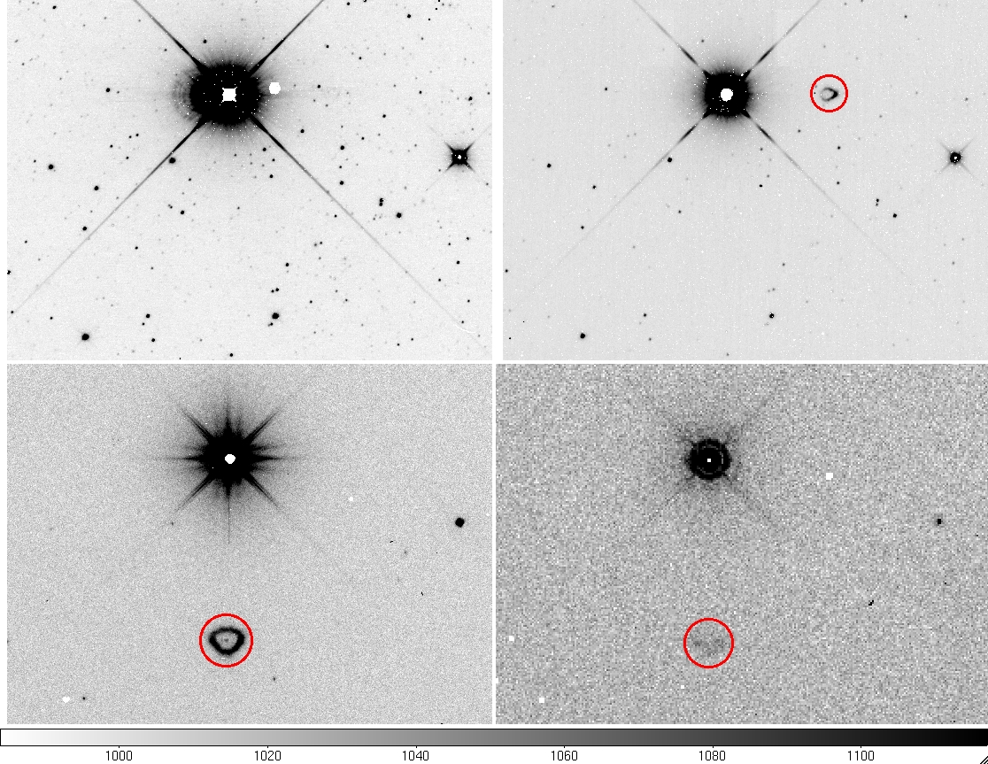 |
| Figure 4 - Examples of ghosts in the four WISE bands. The ghosts are indicated with a red circle and are seen in Bands 2 (upper right), 3 (lower left) and 4 (lower right). Ghosts are generally not visible in Band 1 single-frame images. |
Parameter determination:
For each band, the position of the ghost relative to the center of the parent is assessed, along with the radius of the circular region that is flagged. Table 2 shows values of Δx and Δy, Rghost, mthr_o, and Δmspur_o for ghosts in each band. These parameters were initially determined by inspection of several tens of parent stars, over a range in brightness in each band, and were tuned using test runs of ArtID on single frames. Position and size parameters are given in single frame pixels.
| Band | Δx | Δy | Rghost | mthr_o | Δmspur_o |
|---|---|---|---|---|---|
| 2 | 114.0 | 0.0 | 13.0 | 5.5 | 7.0 |
| 3 (1st ghost) | 0.0 | -206.0 | 25.0 | 4.0 | 6.0 |
| 3 (2nd ghost) | 0.0 | -411.0 | 45.0 | 2.0 | 7.0 |
| 4 | 0.0 | -103.0 | 15.0 | 2.5 | 6.0 |
There is an initial short-term latent that appears to be present at all signal levels above saturation for both the HgCdTe and Si:As arrays. The first frame after the illuminating frame has a latent present at < 0.1% (W1/W2) and 3% (W3/W4) of the peak flux density. The second frame has a 0.4% latent for W3/W4 only. The decay time is ~3 sec. The functional form of the decay of brightness in all bands is modeled as:
 | (Eq. 1) |
where
F0 = initial brightness of pixel in source
0 = decay time = ~3 sec
B = pixel background brightness without source + bias
The short-term persistence behavior for the two types of detectors on WISE have similar decay times and strength; however, the morphology of the latent images is vastly different between HgCdTe (WISE bands 1 and 2) and Si:As (WISE bands 3 and 4). HgCdTe latent images are limited in size to the saturated region of the parent source. Thus, they are rarely more than a few pixels in extent. In contrast, Si:As short-term latent images are up to 100 arcsec in radius and are surrounded by an annular dark halo. The size of the pattern is the same for all saturated sources; however, the S/N of its appearance changes with parent source brightness.
 |
 |
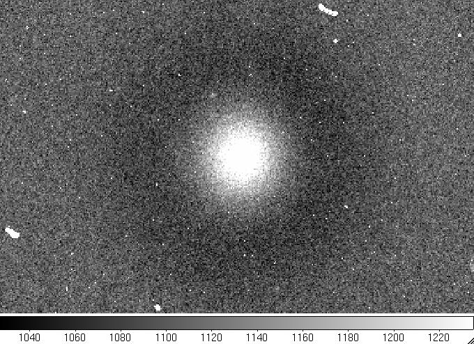 |
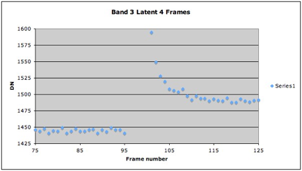
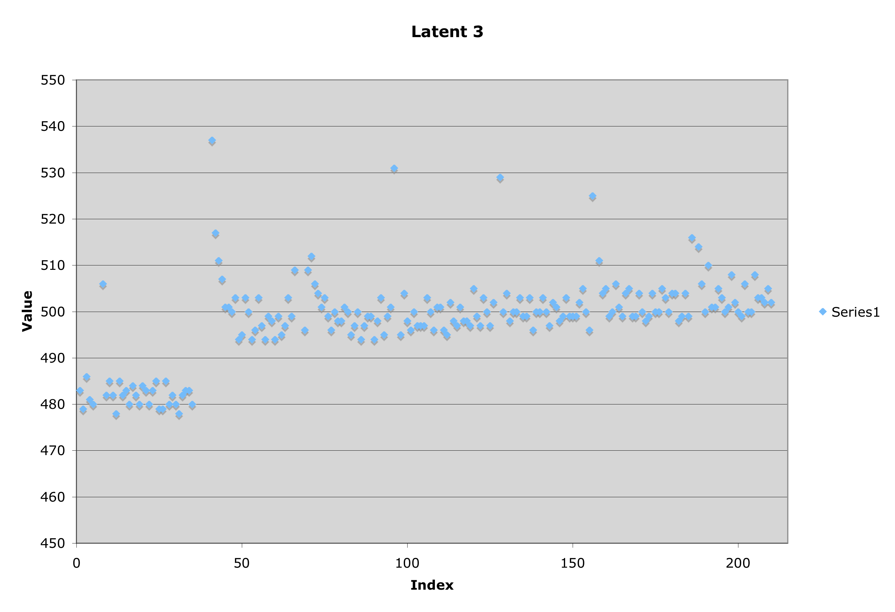
| Figure 5 - Latents in WISE Band 3 introduced by a 95 Jy equivalent source. The displacement between the pixel values before frame 95 and after frame 115 is due to a long-term latent image of about 5% in gain. The exponential decay seen between frames 100 – 105 is due to a short-term latent. | Figure 6 - Long-term latent image in WISE band 4 shown by pixel value offsets introduced by a 32 Jy equivalent source produces an offset in the light curve of about 10% in gain. | Figure 7 - Si:As short-term latent image one frame after very bright W3 source. The entire pattern has a radius of approximately 100 arcsec although the parent source was unresolved. |
Long term latent images appear with hard saturation of the detector. It is a gain effect that increases the response by about 10% in the pixels that exceed the threshold fluence. It is thus similar in extent to the HgCdTe short-term latent. The strength of the latent does not seem to correlate in an obvious way with the brightness of the initial source between 3 and 320 Jy. It is very similar in strength over an order of magnitude in illuminating source flux density. There is no obvious decay in strength of this latent during the 12 hours between anneals, although there is substantial decrease in their strength by 24 hours following emplacement. These latents are completely eliminated by 15K anneal heating of the arrays. Because of the additive correction by dynacal in v3.5, the long-term latents do not appear as spurious sources in the single-frame or multiframe products. However, since they are response artifacts, long term latents may contaminate the photometry of sources that land on affected pixels. For this reason, the position of long-term latents are marked in the v3.5 Level 1b source catalogs and images.
 |
 |
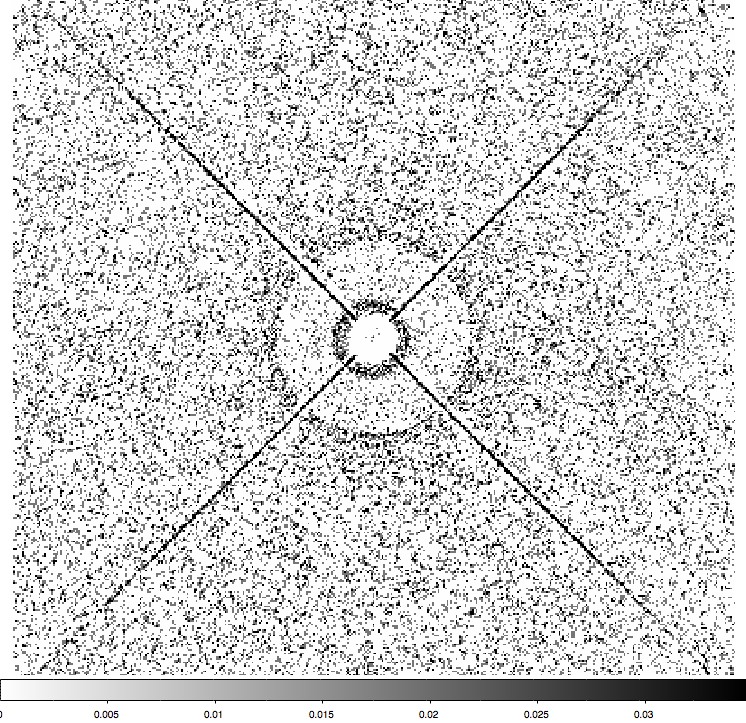
 |
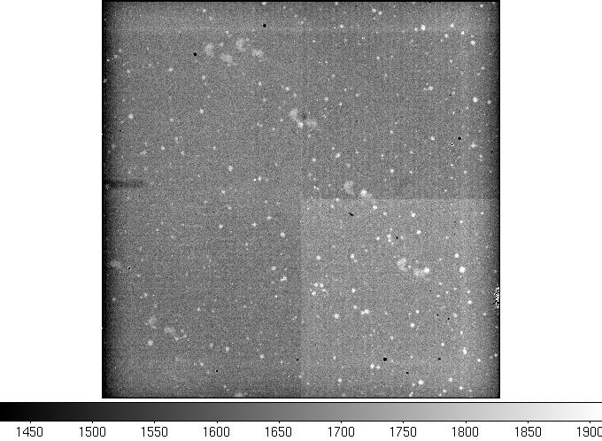
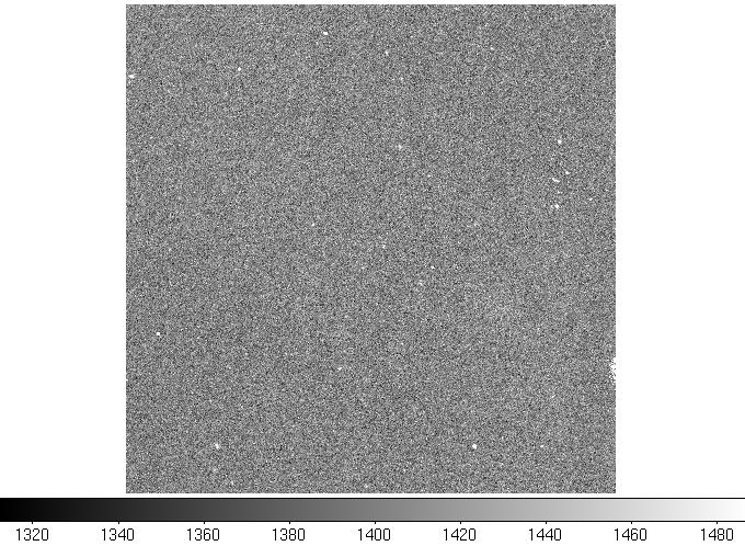
| Figure 8 - "Raw" (Level 0) WISE band 3 image showing long-term latents (bright splotches). | Figure 9 - Preliminary release single frame processing of same W3 image as in Fig. 8. Long-term latents are mitigated through additive correction to frame. | Figure 10 - Mask file for Fig. 9 image. Long-term latents show up as contiguous sets of "transient" pixels in the mask file. These pixels are excluded from source extraction in Level 1b and coaddition in Level 3. |
At flux densities of several thousand Jy, the long-term latent undergoes a qualitative change in character from a positive to a negative gain effect. The dark latent depresses the value of the background by up to 5% in the ground tests. However, over a few hour timescale, dark latents evolve into long-term bright latents. These latents are completely removed by a 15 K anneal. In practice, most of the "dark latents" seen on the Level 1b images are due to oversubtraction by the Dynacal additive correction.
In the WISE pipeline, all types of latents are flagged using a predictive model. Sources above the band-dependent threshold are placed in a latent parent database. The positions of these sources on the array are then tracked on subsequent frames as being potential latent image sites. Table 1 shows the brightness thresholds per band used for determining membership in the latent parent database in the preliminary data release.
| Band | Δmspur | Parent Flux (Jy) |
|---|---|---|
| 1 | 7.0 | 0.16 |
| 2 | 7.0 | 0.3 |
| 3 | 4.0 | 1.0 |
| 4 | 3.0 | 2.0 |
In the V3.5 WISE single-frame pipeline, sources falling within a radius of 8 pixels (3 for W1) from the detector position of latent parents are flagged as artifacts due to the likelihood of their being spurious detections of the latent image. For short-term latents, the latent flagging happens on frames immediately after the parent illumination event and ceases at the point where the decay model predicts the latent will have decayed below the S/N = 5 sensitivity level for a single frame. For long-term Si:As latents, the position occupied by the latent parent continues to be flagged until the next detector anneal.
The cc-flag symbol for latents is "p" or "P" (Persistance). Note that long- and short-term latents are flagged identically by the Multiscan ARTID pipeline and can only be distinguished by examination of the images.
Cautionary Notes - there is a fixed flagging radius for all types of latents in the WISE Preliminary Data Release single frame source catalog. The 8 pixel radius is larger than the size of most short-term latents for W2 and W3/W4 long-term latents, but much smaller than the size of short-term W3/W4 latents. Since the long-term latents persist for up to 12 hours, many more sources may be flagged for long term latents than are substantially affected in the preliminary release catalog. The best way to confirm that a source is affected by a latent is to look at the image. In bands 3 and 4, short term latents will be obvious from their size. If no obvious short-term latent is present, examine the Level 1b mask files and note whether a source of interest falls wholly or partially on a cluster of masked pixels (caused by long-term latents).
Last update: 2012 January 19