


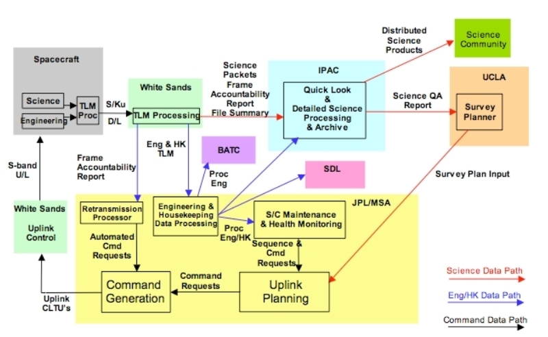
The Ingest subsystem at the WSDC was responsible for assembling Level 0 images from various mission ancillary data products from the Mission Operations System (MOS) and science image data from the High Rate Processor (HRP).
Deliveries include the following:
Ingest has six primary functions:
|
| Figure 1 - End-to-End Data Flow |
Ingest carries out its primary functions in three distinct stages:
The transfer process verified data for completeness and integrity and stored the transferred files on the WSDC operations system at IPAC. Copies of these data were used for the actual ingest process allowing the original data to remain untouched.
Data integrity checking ensured that each file transfer was complete and uncorrupted. Files were compared against their accompanying manifest to verify that file names and sizes were as expected.
A summary of a transfer's contents was created and saved for later reference.
A log file containing a record of all actions taken was then created, saved and subsequently reviewed by the operations staff.
Each time the completion of a new delivery was detected, all data were copied into the operations working directory and validated. All subsequent ingest occurred out of the working directory.
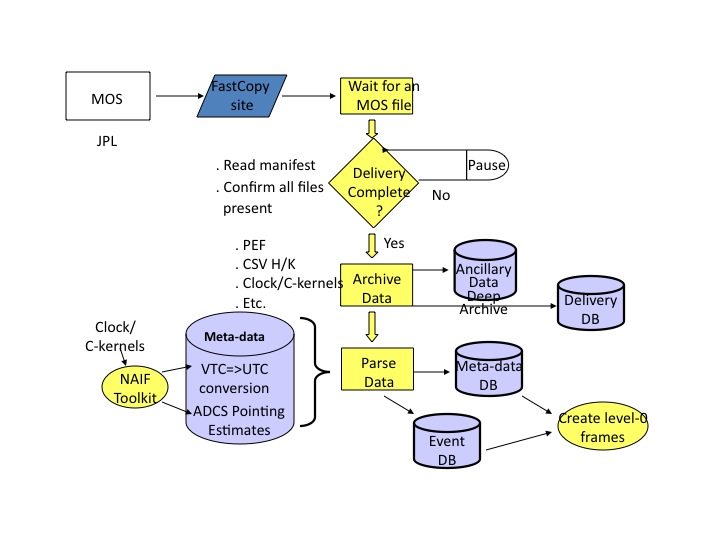
The MOS at JPL is responsible for delivering all ancillary data, i.e. non-image meta-data necessary for subsequent data processing and evaluation.
 |
| Figure 2 - MOS Data Ingest Overview |
Every ingest of HRP data (WISE science images) requires that the following MOS ancillary data be up to date, i.e. the most recent data available must have completed transfer and ingest:
If any of these files were missing or out of date, HRP ingest was aborted, then restarted when all prerequisites were present.The clock kernel files are cumulative, that is, they include data that cover the whole mission up to the final time covered by the file. Thus, each new SCLK kernel ingested simply replaced previous versions.
NAIF library routines are directed by the ingest pipeline to read all C- and SP-kernels within a selectable time window which covers the time period of the data being ingested and they, in concert with the LSK and CLK kernels, then provide all needed functionality for determination of spacecraft position and estimated orientation vs. time.
Various summary statistics and other data were written to a metadata table for each MOS ancillary data delivery.
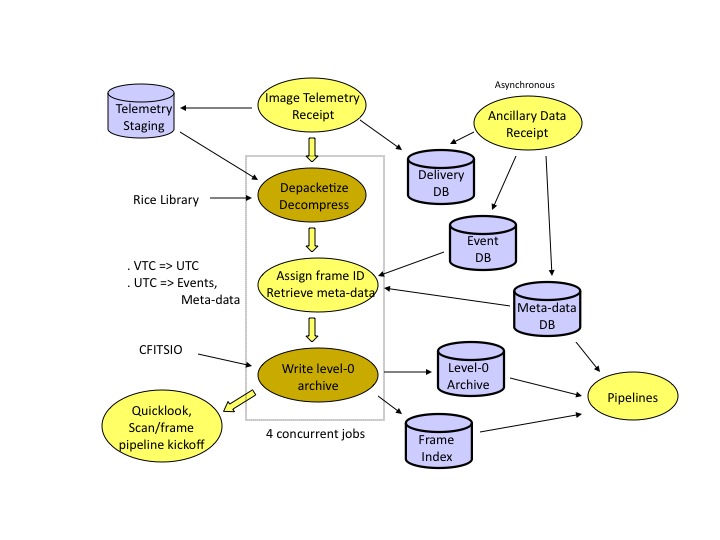
The High Rate Processor (HRP) at the White Sands Complex received telemetry from the TDRSS ground station, stripped off communication packet wrappers and organized the underlying source packets into four time-ordered output files, one each for all images in a given WISE band included in that transfer. These, along with a manifest file, comprised an HRP delivery to the WSDC. In each band's file for a given delivery, images are stored as a stream of compressed images tagged with the image's Vehicle Time Code (VTC), metadata embedded the telemetry (in the CCSDS secondary packet header, to be precise). The ingest process stripped off the telemetry metadata and assembled and decompressed each band into FITS format and rotated the images to a common orientation. These raw FITS images were then associated (correlated) with various mission ancillary data via the VTC (converted to UTC using the SPICE LSK and CLK kernels). This ancillary data, along with standard FITS image definition data, was written to the FITS header. These FITS images comprised the L0 data product and were saved in the permanent Level-0 Archive.
Each delivery included data from an average of about 8 scans. A Quicklook Pipeline was run for a selected subset of the images for each delivery for rapid survey quality evaluation. All completed scans in a delivery were submitted for full processing by the Scan/Frame Pipeline.
 |
| Figure 3 - HRP Data Ingest Overview |
Telemetry files sent from the HRP are time-ordered CCSDS source packets for one band covering the time range for that delivery. The packets were read as streams and the CCSDS packet headers were used to establish the start and end positions of images in the stream, the VTC, and how much data was in the terminal packet (the only one which might have fill data). The data portion of each source packet (i.e. with packet headers and fill data stripped off) for a given image are appended to one another to produce the completed image. The image data was passed to the Rice decompression library to produce a decompressed image. Packet header data, mainly the VTC, was saved for each image for later use.
Every packet header was examined for internal consistency by checking the following:
If any of these checks failed, the packet was assumed to be corrupted, an error generated, the image was skipped and ingest processing continued.
If all checks were successful, the raw image was ready for correlation with the ancillary data.
To be processed by the Scan/Frame Pipeline, image data must be associated with mission ancillary data. All ancillary data was either present, or processing could not continue. The ancillary data required is listed below in rough order of importance:
Other SEQGEN files, such as the mission plan file, were also delivered, but these were not used in Level 0 image construction.
All data listed above were queried by image VTC to get the requested data. These data were then saved as metadata associated with the image and in the Level 0 image FITS header.
With the raw image and correlated ancillary data in hand for each image, the Level 0 FITS image is created as follows:
The event table provides start and stop times for science scans, and with them a unique scan ID for that scan. The scan ID was derived as follows:
For example, suppose the PEF lists the orbit number as 1506.5 after a particular SEP crossing. The half-orbit number is 3013. The second scan that starts in this would produce the scan ID 03013b.
"Frame numbers" (a frame is an image and associated
meta-data)
were assigned to each image based on the
time elapsed from start of the scan (as recorded
in the event table) to the start of the image's exposure in
integer counts of 10 second bins as follows:
Some of the metadata associated with each Level 0 frame were written to the Frame Index, a set of RDBMS tables that tracked important image information and the progress of every frame as it was processed. The key data in the Frame Index are:
The image center position, spatial bin, and frame time columns were indexed.
Subsequent processing, such as by the Scan/Frame Pipeline, updated other columns in the Frame Index to track processing progress and record QA data.
Ingest of the image telemetry packet stream occasionally generated errors due to packets being corrupted or lost in transmission. When this happened, the corrupted image was discarded and processing continued after resyncing to the start of the next image in the stream. All complete images not affected by corruption were ultimately extracted from a telemetry file.
Frame accounting was done on an ongoing basis to ensure there were no major communication problems. This accounting was entirely advisory as it was not possible for the WSDC to initiate any actions to retrieve missing data.
When frame images were lost in communication from the satellite to the WSDC, they were often, but not always, retransmitted by an automated accounting process at MOS. Thus images for a given scan may occur not only separated into multiple deliveries but out of order. In any given ingest run it was therefore impossible to know what missing frame data in a scan might ultimately appear. Thus frame accounting could only be done well after ingest completed, when no more frames for a scan could be downlinked.
Counting missing frame data was done in a few different ways:
The Scan Pipeline was started for every scan which had all expected frames, or for which a drop-dead time interval since the last frame to be received had passed. The Scan Pipeline would in turn start an instance of the Frame Pipeline for every frame with Level 0 image data.
Ingest created the output directories for frames known to be present in the scan and the Frame Pipeline linked to the Level 0 images for that frame and copied ingest meta-data. These, the Frame Index, and static calibration data form the prerequisites for Scan/Frame processing.
Meta-data files recording detailed information for all frames received was saved with the Level 0 archive and in the Scan/Frame Pipeline processing directories.
For each delivery, the ingest process started one Quicklook pipeline to run on approximately 100 frames per delivery to get an immediate, preliminary look at data quality. Frames were selected based on the sky location exposed, statistical properties, calibrators in-field, and observation time,a s well as a population of random frames. The selection criteria were meant to emphasize frames that will give clean PSF measurements to confirm that the scan mirror is in sync with our scan rate.
The Quicklook Pipeline is the Scan Pipeline with command-line parameters set such that:
A composite PSF was generated by Quicklook combining data from all the frames selected, and its properties were evaluated to confirm scan synchronization.
Last update: 2012 March 15