

 |
Spitzer NEP Data Reduction |  |
READOUT_MODE: FULL_ARRAY
ARRAY: 3.6_5.8u=YES, 4.5_8.0u=NO
HI_DYNAMIC: YES
STELLAR_MODE: NO
FRAME_TIME: 12.0
DITHER_PATTERN: TYPE=none
N_FRAMES_PER_POINTING: 1
MAP: TYPE=RECTANGULAR, ROWS=18, COLS=18, ROW_STEP=156.0, COL_STEP=156.0,
RIENT=ARRAY, ROW_OFFSET=0.0,COL_OFFSET=0.0,N_CYCLE=1
SPECIAL: IMPACT = none, LATE_EPHEMERIS = NO,SECOND_LOOK = NO
RESOURCE_EST: TOTAL_DURATION=8908.7, SLEW_TIME=1808.8,
SETTLE_TIME=0.0, SLEW_OVERHEAD=215.0, SPECIAL_OVERHEAD=0.0, UPLINK_VOLUME=15960, DOWNLINK_VOLUME=195950664
VERSION=S16.0.0
INTEGRATION_TIME: IRAC_3_6=12.0,IRAC_4_5=12.0,IRAC_5_8=12.0,IRAC_8_0=12.0
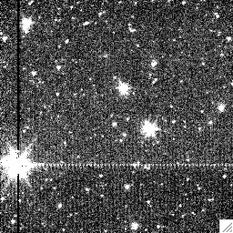
Example: IRAC-1 BCD |
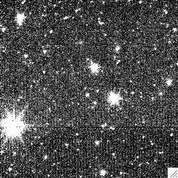
Example: IRAC-1 BCD after artifact correction; note the column pulldown is now absent and the muxbleed is greatly improved. |
2. Additional corrections are needed to IRAC-3 BCDs to correct for first-frame residual gradients across the focal-plane.
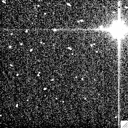
Example: IRAC-3 BCD with residual dark current (note the background gradient). |
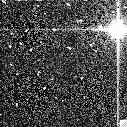
After delta-dark correction |
Here is an example of an IRAC-3 mosaic that looks like a patch-work quilt due to this phenomenon. And here is the same mosaic after carrying out delta-dark subtraction.
To create "delta dark" images to subtract from the BCDs, you do this by building optimal median combinations of the BCDs themselves. To quote from the IRAC handbook:
3. Overlap correction: using MOPEX, run the overlap correction module for all channels.
4. Combine the overlap-corrected BCDs into one large mosaic (per channel). The following date sets are used:
5. The last step is to derive the array-location dependent photometric corrections. This step is needed if you intend to measure stellar fluxes from the mosaics. The corrections range +- few %.
The procedure is this: create a set of "fake" BCDs that have the actual WCS coordinate info from each BCD, but the pixel values correspond to the array-location correction images. With these "fake" BCDs, combine together with MOPEX with the usual file lists, *except* use the previously derived "R-masks" (found in the directory "Rmask-mosaic" where the MOPEX results are collected). These R-masks contain the rejected pixels (usually due to cosmic-rays), and so you will be simulating the actual pixel coverage of your mosaics (Step 4, above).
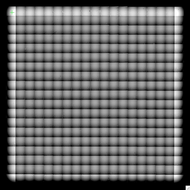
IRAC-1 array-location correction mosaic; values range +- 1%. |
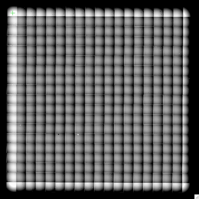
IRAC-2 array-location correction mosaic; values range +- 1%. |
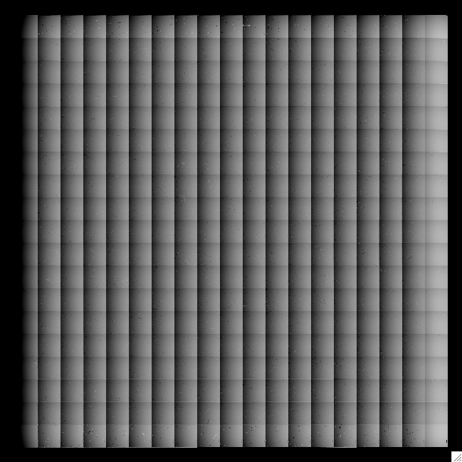
IRAC-3 array-location correction mosaic; values range +- 5%. |
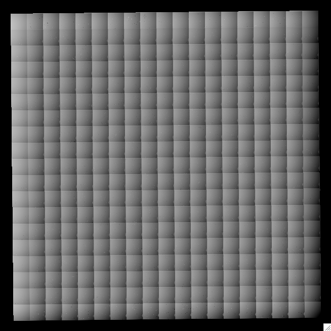
IRAC-4 array-location correction mosaic; values range +- 4%. |
Special thanks to Frank Masci and Betsy Hall for help with the artifact mitigation step (#1).